This is a collection of bits and pieces that may help you with some of the projects in Building Recreational Flight Simulators. Probably of most interest, at least initially, are the printed circuit board design files and the micro controller programming hex files.
When I first started developing projects I made the circuit boards at home using the toner transfer method. However, as I read about people's approaches to making boards, it became apparent that the DIY methods were not so popular as having professional boards made. After taking a closer look at the professional options, I began to use professional prototyping services myself.
There are two general paths you can take along the professional route. You can use any of several PC board design software applications and develop industry standard (Gerber/Excelon/etc.) files which you then send to the PC board house of your choice. Alternatively, you can first choose among a limited number of board houses and use (usually free) proprietary board design software which ties you to that board house.
The first approach requires finding and learning how to use the PC board design app. Several design apps have free, "lite" versions which are limited to some small number of devices, holes, and/or to a small amount of board area. To develop larger, more complex boards you must pay a licensing fee. These applications are powerful, complex, and time consuming to learn. If you're interested in electronics and plan on developing a lot of different circuit boards of which you will make many copies, this is probably the approach to take. Make a time and money investment up front then shop around for the lowest board production costs.
The second approach allows you to develop boards of moderate complexity. The software is free and easy to learn, but you'll be locked in with the PC board house that provided the software. You may not get the absolute lowest cost on the board production, but you'll have almost no up front costs. If you're using electronics as a means to an end, and will only need a few boards, this is a good approach.
I chose the second approach part way through developing the projects for Building Recreational Flight Simulators. I used the software and services of ExpressPCB.
I am making the project circuit board design files available for free for non-commercial use on an as-is basis. I'm doing this primarily for people who have purchased Building Recreational Flight Simulators. Documentation for these projects is in the book. To use these files you'll need to download the design app from ExpressPCB.
Caveat DIYer
I have no business relationship with ExpressPCB other than as a customer. If you purchase BRFS project boards from them, the transaction is strictly between them and you. To the best of my knowledge the design files are correct, but I have made and continue to make mistakes, (as I am frequently reminded by my children). I do not warrant the board design files to be error free. Unless otherwise noted, they worked for me, but maybe that was because it was full moon. Please double check the file before ordering boards.
Position and Force Sensors Chapter
LVDT Electronics Project
This is one of the projects that I prototyped DIY messy style at home. Currently I have no ExpressPCB design file for the board.
I/O Options Chapter
I/O Bus Adapter Project
This is a simple RS-232 to RS-485 adapter. You can use it to convert the serial com port to a multi-drop serial bus. I had the printed circuit board made by ExpressPCB.
You can download the ExpressPCB format circuit board file here.

Bus Input Arbitrator Project
This project allows several devices to cooperatively share a single com port while inputting data to the host computer.
Download the ExpressPCB-format circuit board file here. You'll need the design software from ExpressPCB to open it. When you do it should look like this:
Download the micro controller programming hex file here.
Using Real Instruments Chapter
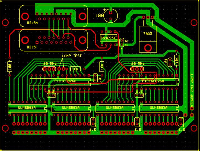
Digital-to-Synchro Converter Project
This project allows you to create the S1, S2, & S3 signals needed to drive synchro-based instruments and gauges.
CAVEAT: This is a copy of the artwork I developed and debugged for the prototype. I have not tested this particular version. I believe it to be correct, but it may contain errors.
Download the ExpressPCB-format circuit board file here. You'll need the design software from ExpressPCB to open it. When you do it should look like this:

Download the micro controller programming hex file here.
Digital-to-Synchro Project Revision
The DTS circuitry has caused a bit of heart burn for a few builders. The source of this gastic distress is the operation of a clamp transistor that inverts the polarity of an analog signal.
Originally I used a 2N7000 switching FET, choosen for its low on resistance. The problem is that the 2N7000 does not work well when the drain is more than a few tenths of volt more negative that the source. The original thought was that the circuit would handle only small signals. In retrospect, that was a poor choice on my part. Component variation and the range of signals passed through the inverter stage differed from my prototype.
An N-channel JFET makes a better clamp. If the gate-source voltage is held at zero, the transistor acts like a low value resistor. If the gate is pulled 8 or so volts more negative than the source, the transistor turns off, acting like a very high value resistor. It's just what you want for a switch.
Almost.
One issue is that the minimum resistance of most JFETs is on the order of 100 to 200 Ohms. Something in the single digits would be better. A little shopping around found a few JFETs that fit the bill. The J108, J109, J110, PN5432, PN5433, and PN5434 are suitable.
A second issue is that while the 2N7000 is switched by the 0 to 5 volt logic level from the DTS microcontroller, N-channel JFETs require a negative voltage if they are to be switched off. Fortunately the DTS uses TL084 quad opamps and there are a few uncommitted amps available. A few resistors and the opamp changes the logic voltage to the required negative going gate voltage.
A caveat: I've breadboarded the inverter section and it works as expected. However, I have not been able to test this mod in a functioning DTS. Also, note that this mod inverts the sense of the sign bit, requiring a small firmware mod.

I have added these revisions to the circuit board layout. There are no guarantees that the new layout is correct; to the best of my knowledge it is, but I have not built and tested it. Please check it before using. Your eyes may well find something I missed.
You can download the revised PCB artwork here. It should look like this:

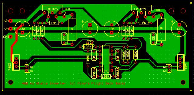
400 Hz Static Inverter Project
This project generates a moderate amount of 400Hz power.
CAVEAT: This is a copy of the artwork I developed and debugged for the prototype. I have not tested this particular version. I believe it to be correct, but it may contain errors.
Download the ExpressPCB-format circuit board file here. You'll need the design software from ExpressPCB to open it. When you do it should look like this:
DIY Instruments Chapter
Stepping Motor Based VSI Project
This project interfaces a hybrid stepping motor to a serial data link so you can create steam-gauge style instruments.
CAVEAT: This is a copy of the artwork I developed and debugged for the prototype. I have not tested this particular version. I believe it to be correct, but it may contain errors. (It's simple! how far wrong could it be?)
Download the ExpressPCB-format circuit board file here. You'll need the design software from ExpressPCB to open it. When you do it should look like this:

Download the micro controller programming hex file here.
Two possible stepping motors for use in this project are the 28M054 from Alltronics.com and the 1581231 from Jameco.com.
Dual LED Gauges Project
This is another project that I prototyped DIY messy style at home. Currently I have no ExpressPCB design file for the board.
Switch Input Chapter
16 Switch Input Module Project
This project interfaces 16 switch closures through a serial data connection to the host computer.
Download the ExpressPCB-format circuit board file here. You'll need the design software from ExpressPCB to open it. When you do it should look like this:

Download the micro controller programming hex file here.
LCD Radio Head Project
This project is a radio control head based on a small LCD character display and a simple rotary encoder. It interfaces to the host computer through a serial data link.
CAVEAT: This is a copy of the artwork I developed and debugged for the prototype. I have not tested this particular version. I believe it to be correct, but it may contain errors.
Download the ExpressPCB-format circuit board file here. You'll need the design software from ExpressPCB to open it. When you do it should look like this:

Download the micro controller programming hex file here.
Warning & Status Lights Chapter
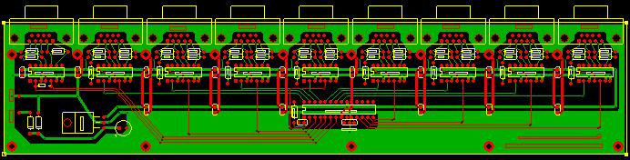
Warning Lamp Electronics Project
This project interfaces 32 ground side output switches to the host computer through a serial data link. As described in the book this is used to drive 32 LEDs, but if you're clever you can interface all sorts of things.
Download the ExpressPCB-format circuit board file here. You'll need the design software from ExpressPCB to open it. When you do it should look like this:
Download the micro controller programming hex file here.
Sound Chapter
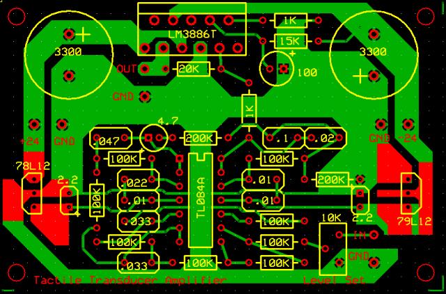
Tactile Transducer Amplifier Project
This project is a power amplifier with an integral low pass filter on its input. It's meant to be used to drive bass-shakers/tactile-transducers.
Download the ExpressPCB-format circuit board file here. You'll need the design software from ExpressPCB to open it. When you do it should look like this: