
FSX SDK & Multiple Monitors under WinXP (28 Dec 2006)
Learning SimConnect
I'm drifting into software mode. I plan on including code samples in my upcoming book that show how to interface simulator hardware to Microsoft FSX. So, I've begun working through the code examples in the SimConnect SDK.
In the beginning, this is really an exercise in properly configuring the coding environment. The fact that the code examples compiled and worked for ACES team members is no guarantee that they will work for any random hobbyist.
Like me, for instance.
I don't have the experience of an ACES team member, a building full of talented and helpful people to call upon or anywhere near the software development tools they have. But, hey, that's all part of the challenge and fun!
The SimConnect SDK specifically says that the express version of Visual Studio and VC++ can be used to compile and run the code examples. What is doesn't say is that the express version is not all that's needed. When first trying to compile the "open-close" example, it didn't get past the first include directive. Seems the express version of VS doesn't come with the headers for building windows apps.
These are trivial issues for those with even moderate programming experience. They are rather more challenging for those just beginning. If you're just starting you will need to:
- Install the express edition of Visual Studio and VC++.
- Install the Windows platform SDK (free from Microsoft)
- Add a path description in Visual Studio's configuration that points to the folder holding the simconnect.lib file.
- Don't forget to put a copy of simconnect.h in you code project folder.
Fortunately, there are some good resources for us beginners. If you're into C#, visit NotASenator's Blog for a growing list of tutorials. For general questions, you can peruse the SimConnect forum at AVSIM. To tap into some high level discussions, visit the SimConnect wiki and forum at FSDeveloper.
Multiple Monitors
I'm slowly exploring multi-monitor configurations for use in flight sim. I'd like two or three monitors for scenery display and a fourth for a soft instrument panel. I intend to experiment with Fresnel lenses, and find out just how far I can push a single processor sim system. The SLI video card configurations look attractive, but I'd like some first hand experience before talking them up in the book.
I've got a GeForce 6800XT video card. It's a dual headed beastie that gives reasonable bang for the buck. It's capable of SLI pairing, though I've not yet bought a second card. For a while I ran a pair of Samsung SyncMaster 740N LCD monitors (with analog inputs) on the single 6800XT. All-in-all, not too bad. Then my daughter left for college, taking monitor number 2 with her.
Newegg had a sale on 19 inch LCD monitors, so I bought a Samsung SyncMaster 941BW. It's a wide screen model with 1440x900 resolution. Unfortunately I couldn't get it to play well with the 740N in dual monitor mode. When Newegg had another sale I bought a second 941BW.
I've had on heck of a time getting the two 941BWs set up in a multiple monitor configuration. Just plugging them both into the video card caused Windows to blue screen before it could finish booting. After updating drivers, I was able to have them both plugged in and boot successfully, but still got the BSOD when I tried to enable the second monitor. I finally got a dual monitor config working by using analog inputs on the monitors.
This offends me because the video card has dual DVI outputs. The monitors have both analog and digital inputs. It's digital data into the video card, digital data out. LCDs screens are digital. I should be able to use a digital connection. It really, really annoys me that I can't and don't understand why.
The electronic gauge project is working (4 Dec, 2006)
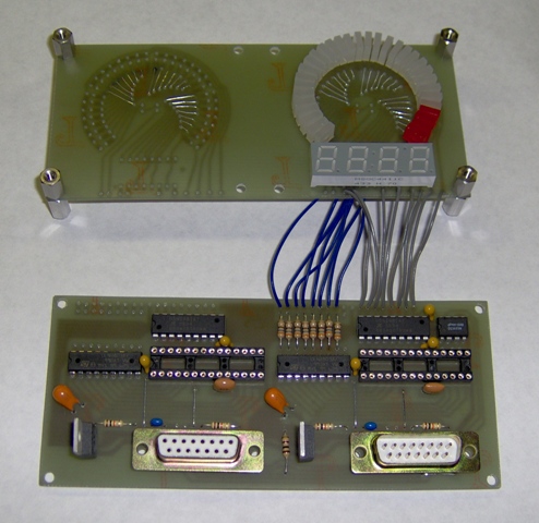
The prototype for dual LED-based electronic gauge project is turning on its LEDs and digits under computer control. Most of the debugging issues were the result of writing firmware for a PIC16F628 and expecting it to run on a PIC16F876A. It's the same instruction set, but the 876A has a few extra control registers and its control bits are not always in the same place as in the 628. Well, "RTFM", as they say.
With apologies for the poor photos, here's what it sort of looks like. The pictures don't provide the same contrast you get when viewing them for real. The fuzziness, however, accurately depicts what I see after working on projects for too long.

Both sides are displaying the same numbers because I haven't gotten around to giving the two sides different instrument IDs.

Here's a shot showing the project pretty much buttoned up. Guess I should put a couple of small heat sinks on the voltage regulators. They get a bit warm to the touch . I'll do my standard piece of scrap metal trick.
The two connectors are data in and data out. The project uses an RS-422 multi-drop connection that can be daisy-chained through a fair number of devices.
Revisiting the DIY Instruments chapter and the electronic gauge project (28 Nov, 2006)
I have a strong draft of the DIY Instruments chapter. It overviews the use of stepping motors, air-core movements, RC servos and LEDs for making instruments. It's a big chapter because instruments have an important role in building and supporting the flight simulation illusion.
There are two projects. The first is a updated stepping motor based VSI. It uses a PIC16F648A micro controller and communicates through a multi-drop RS-422 serial connection. Using a very simple RS-232C to RS-422 converter, a reasonably large cluster of devices can hang off a single PC serial com port. (Plans for just such a converter are included in another chapter.)
The second project is an electronic gauge patterned after the gauges that were developed to replace their electro-mechanical cousins. This project has a 270 degree arc of 32 LEDs that mimics the motion of a physical pointer. Just below the arc is a 4-digit, 7-segment display that gives a precise reading. The project description includes a set of circuit board layouts for a pair of side-by-side gauges. They share the I/O connectors and data receiver, but otherwise are separate gauges. You could stack half a dozen of these dual modules on an instrument panel for your engine gauges. Bussing the power connections and the received serial data line would give you a cluster of gauges that needs only a single cable connecting it to your sim.
The first version of the LED gauge was based on a 3" instrument. I made the boards for the prototype, but decided there was too much room between the LEDs. I didn't have enough I/O pins on the micro controller to add more LEDs, So I decided to try reducing the gauge to a 2 inch diameter arc. This turned the redesign into a major pain, but finally seems to be working out.
It would be much easier (for me) if I used double sided circuit boards, but I am restricting the board designs to single sided. The rationale is that it's much easier to make a single sided board at home. If the people who buy the book want to use double sided boards, they will most likely use a commercial board prototyping service. This will require them developing a board layout in an electronic format. If they're going to do that, it's a small step to convert to a double sided design. However, if I present an optimized, double sided design in the book, it can be a real pain to convert to single sided for the guy who wants to build the boards at home.
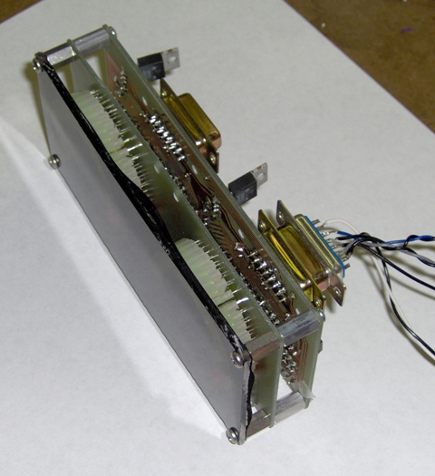
Here are a few pictures of the 75% built prototype. (I won't add the rest of the LEDs until I get the firmware updated. No point in frying any more LEDs than necessary.)
The logic board mounts behind the LED board. This assembly will mount to a clear plastic front piece. There will be a thin transparency just behind the plastic front. The transparency will have the gauge legend printed on it and will mask everything but the LEDs and display.
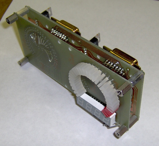
The 7-segment display and the bulk of the LEDs emit green light. There are four red LEDs at the end of the arc to indicate an overrange.
I had the firmware pretty well together for the earlier, 3 inch version. With the size reduction I did some major I/O pin reassignments to the micro controller. This means all the port write commands must be changed.
So that's where I am now, revising firmware. Then I have a few drawings and paragraphs to update. Once all that's done, the DIY Instruments chapter should be pretty well done.
(Hmmm, been a long time since I powered up the stepping motor VSI. Guess I should re-assemble the code, making sure it works with the current free version of MPLab, and make sure it flashes the PIC properly. Oh, it'll work, np, right? right???)
Fuel Flow Gauge, Hall Effect Sensor, Wrapping up a Chapter (14 Nov, 2006)
I picked up an interesting looking dual fuel flow indicator through Ebay. One of the needles was pointing off zero and I though perhaps the unit was synchro based. Turns out that wasn't the case, but it was still a worthwhile purchase.

The indicator is actually based on moving-coil movements. The movements are situated one behind the other. Gears and an idler shaft route the torque from the rear movement around the front unit. Only the pointer assembly is concentric.
Indicators like this one are easy to interface to a simulator. I will take a wild guess and say you could probably use the indicator without modifying it. Although I've yet to trace the circuitry in the unit, fuel flow sensors aren't terribly complex in their signaling protocols. It should be straightforward to simulate that and wire to the connector on the back on the fuel flow indicator.
Of course, there is an even more straightforward approach. Simply remove the indicator electronics entirely and talk to the moving-coil movements directly. They speak DC (direct current) which is about as simple a signaling protocol as you will find anywhere. This indicator is a good candidate for a PIC16F648A micro controller running a PWM (pulse width modulation) routine. The PIC has a serial interface which can talk to a PC com port (or USB-serial port adapter), so all-in-all it should be a pretty easy conversion to simulator service.
Hall Sensors
Rotary Hall effect position sensors are quite the rage for replacing flaky potentiometers. Hall effect position sensors don't have sliding electrical contacts, so they don't suffer that kind of failure. They still fail, but they have a very, very long lifetime. The downside is that they are priced like something that is expected to last forever. Just for fun, I thought I'd look into what's required to build a Hall effect position sensor.
The key element, not too surprisingly, is a Hall effect sensor. It looks like a transistor and costs less than a US dollar. The ones I got (Allegro A1310 Linear Hall sensors) have a sensitivity of about 1 milli-volt per gauss. They take 5 volts as power and produce about 2.5 volts output in the absence of a magnetic field.

I used a small ceramic magnet to put the sensor through its paces. Above, you see the sensor producing an output indicating little or no magnetic field. When I move the magnet close to the sensor, the output increases in response to the field.
When I turned to magnet over, the output voltage dropped below 2.5 volts, indicating a reversal in the magnetic field.

A good position sensor is more than a magnet and a Hall effect sensor. A good position sensor should respond linearly to position changes. While the Hall effect sensor does respond linearly to magnetic fields, the field around the magnet does not change linearly with distance from the magnet surface. You can't simply wave a magnet near the sensor and get a linear output in response to magnet position.
Producing a magnetic field that varies linearly with some sort of physical movement requires a magnetic circuit. It will have a magnet as the source of the field and a few pieces of high permeability material to direct the field. Designing a magnetic structure isn't difficult. The problem is locating appropriate materials. Ideally, the material will conduct the field well (that's what permeability means), but it will not itself become magnetized. This is referred to as zero remanence.
If the magnetic circuit becomes even slightly magnetized, there will be a ghost of the earlier positions of the magnet. This causes an error in the position sensor output. It's not an error that can be calibrated out. As the position sensor actuator moves, the ghost drifts along with it.
The most common material used in magnetic circuits is annealed mild steel. It's got great permeability but only low remanence. There are various alloys that have near zero remanence, but they tend to be expensive.
It may be possible to make a useable Hall effect position sensor using mild steel. The remanence induced error might be minimized enough to not be an issue in some applications. I'll have to save that for some future musing, however. Right now I've got a book to finish.
Book Progress
Speaking of which, I've got the Position Sensors chapter just about wrapped up. I made a few late changes in the project (a pair of LVDTs and accompanying electronics) that I need to verify. I think a few of the drawings could be improved a bit as well.
Oh, I finally got my copy of FSX. At some point I have to submerge myself in SimConnect. I plan on providing some source code for interfacing some of the book projects. We shall see.
Position Sensors Chapter and LVDT Project (27 Oct, 2006)
I have a good draft of the chapter on position sensors, but is it complete? There is always a question of how much to put in a chapter. In this case, it's how many sensors to cover, and with how much detail. There are many additional topics that will interest (and be useful to!) at least a few people. Unfortunately adding more material is worse than simply being "diminishing returns". Not only does adding more and more material interest fewer and fewer people, the book costs more and the publishing date moves further out.
Case in point is strain gages. These are resistors that change value when mechanically deformed. They measure force by responding to the minute changes in position or shape that results from the applied force. They are useful in a simulator that has force activated controls. The F-16 has force activated controls, but uses LVDTs as the transducers. The F-16 radar control curse is force activated, but uses a beastly expensive, high-output silicon strain gage. The expense puts it out of reach of all but a lucky few.
So, hmmm, mumble, mumble, looks like a section on strain gages would be mostly of academic interest. Given that this book is a practical, hands-on kind of book, it would seem that strain gages shouldn't be in the book.
On the other hand, Leo over at Beta Innovations, has made accommodations for interfacing load cells. Load cells are basically strain gages in a calibrated mechanical assembly. Small load cells are the weight sensors in some models of electronic scales. The race car sim crowd is beginning to look at these load cells for measuring clutch and brake pedal pressure. I haven't seen much mention of them in the flight sim community as yet. But if Leo's working with them, load cells clearly have merit. Hmmm, mumble grumble, decisions, decisions.
The chapter project is a pair of LVDTs and a signal conditioner. This is an improved version of the LVDT I posted a few years back. One of the LVDTs is a short stroke model you might use for force activated pedals. The other has a stroke of several inches and would be useful as a throttle position sensor. The signal conditioner is a small circuit board that has the oscillator that excites the LVDT primary, and the detector and amplifier that produce a 0 to 5 volt output for interfacing to a PC.
The original prototype is pictured below on the left. The circuit board on the right is the actual chapter project. The paper underneath them are a few pages from the manuscript which are already collecting a few red correction notes.

The circuit board designs in the book are all single sided. This means there will generally be a few jumpers (this board has two), but also means it's easy to make the boards at home.
I made the circuit board using Press-n-Peel printed circuit board transfer film. This is a toner transfer film that you send through a laser printer. You use a laundry iron to transfer the pattern of toner to the copper circuit board material. I had done this sort of thing before using photo paper. I was getting okay results with the photo paper, but it was a pain getting the paper to let go of the toner once the transfer was complete. You have to soak the paper in water then shred it, and scrub it and plead with it to please let go. The paper is slightly less expensive than the film, but it just wasn't worth the hassle any more, so I bought some film designed specifically for the task. It was a new learning curve.
The first attempt melted the film and gummed up the iron. Okay, I hadn't actually READ the directions. I just sort of skimmed them, apparently missing the part about how critical the temperature would be. The second attempt was better in that the film didn't melt. However, I had pushed too hard. The film slipped sideways a bit. The pattern was transferred but was squashed and smeared. On the positive side, I didn't have to clean out the iron this time. The third attempt got workable results. The center was a bit squashed and one edge didn't transfer properly, but it was nothing that couldn't be fixed with an Exacto knife and a bit of Scotch tape.
Small Power Supplies and Big 7-Segment Displays (17 Oct 2006)
With the kids in college, the dog home from the vet and the wife at work, I've been trying to make some serious progress on Building A Recreational Flight Simulator. I've read a lot a "how to write" self-help books. So far the common thread is some version of "plant your butt firmly in a chair in front of a keyboard". Not very high tech, surprising hard to follow, but actually quite effective. So, for the past week I've been beating on the "Position Sensors" chapter (to good effect, I think).
Position sensors are the transducers that translate the physical movements of flight sim controls into electrical signal that the simulation computer can use. I'm covering the four that I think are most important to us flight sim hobbyists: potentiometers, Hall effect sensors, LVDTs and synchros.
Pots are the staple position sensor of flight sim. Need to measure some random motion? Stick a pot in. They're in joysticks, gamepads, pedals, throttles, you name it. But how do you select one when you're going DIY? How do you know if a pot's NOT the best choice?
Maybe you've heard that a Hall sensor is the ultimate way to go. Well, maybe it is. Or maybe not. What's a Hall sensor anyway? And why does it cost so much?
You could use a linear variable differential transformer (LVDT), except with a name like that it's probably insanely complex and obscenely expensive. Actually, no on both points. In fact it's simple enough you can build them yourself. And they never, never, never "spike" like a worn out pot.
And then there are synchros. You probably won't build something that incorporates a synchro, but there's a very good chance you'll end up using something that has synchros in it if you use surplus instruments. Synchros are widely used in military and commercial avionics. If you plan on using surplus avionics, you need to know what's going on inside synchros.
Finally we come to rotary encoders, except that would be position sensor number five, so I won't cover it. At least not in this chapter. Check the chapter on switches.
Fortunately, I get some time away from the keyboard. I have to build all the projects, and I just got some new stuff. For example I ordered some switching power supplies. I knew they would be small, but even reading the dimensions in the catalog didn't communicate how compact they can be. I suppose it's because I'm used to bulky linear power supplies. The supply picture below is a 24 volt, 1.5 amp unit. Small. Doesn't weight much either.

The 7-segment displays below will become part of an electronic engine instrument. It will be surrounded by an arc of individual LEDs that mimic the movement of an analog gauge pointer. This is the second project in the DIY Instruments chapter. The chapter itself is pretty well done, but I haven't verified that the project documentation is correct. Gotta build it for that.

Today is the official release date for Microsoft FSX. I placed a copy on order some time ago. Sure hope it shows up soon. I have a couple chapters that refer to specifics about interfacing and customizing. My notes based on FS9 are no doubt horribly outdated. I'm looking at a lot of time reading the SDKs and trying different ideas.
Synchro Ground Isolation (9 Oct 2006)
I had been struggling with the issue of synchro signal ground isolation. Quite a number of commercial and military aircraft instruments incorporate synchros. "Synchro standard" signals are often sent to these instruments to make them do their thing. Most often, these signals are isolated from ground.
There are valid signal integrity issues in a complex aircraft for this ground isolation. But, truth be known, as long as the proper voltage relationships exist on the synchro terminals, the synchro doesn't much care if one of the terminals is held at ground or not. If you're not in a complex aircraft, signal integrity is not generally an issue, and ground isolation isn't needed.
I used this fact to good effect in the digital-to-synchro (DTS) project. I "defined" S3 as ground. (Engineers have god-like powers.) It simplified the project making it lighter, smaller, cheaper and easier to build.
But what if some instrument designer, years ago, decided to do something strange? What if, say, S2 is grounded inside the instrument? What if the instrument just won't work without signal ground isolation? Then we wouldn't be able to interface a surplus instrument of that type in our simulators using the DTS project. Now, that really shouldn't be the case. But, well, what if?
So, being only slightly paranoid, I decided to come up with some optional way to provide ground isolation, just in case. My problem wasn't that I couldn't come up with a way to do it. It was doing it cheaply.
In avionics you typically use a Scott-Tee transformer arrangement (shown below) to provide ground isolation. It also translates between a set of two signals having a 90 degree relationship ("resolver" signals) and a set of three signals having a 120 degree relationship ("synchro standard" signals). It seemed a ready made solution.

The problem was that Scott-Tee transformers are expensive.
Excuse me. I understate the problem. They are EXPENSIVE! Even on Ebay!
Not a problem, I thought. I will cleverly adapt some common transformers to the task and amaze my friends (or at least myself). And I proceeded to do so. Turns out you can fudge some of the transformer turns ratios IF you can make compensating adjustments in the circuitry it connects to. Well, I could, so I did, using a pair of surplus power transformers. Then I went about documenting my amazing feat for book 2, and discovered that there was no reliable source for these transformers. Publishing a project that requires unavailable parts is über seriously, unforgivably un-cool.
Angst and heartburn! I had amazed no one (not even myself).
And then I had an Aha! moment. (Okay. Actually, it was more of a Duh?, Duh! moment)
The Scott-Tee connection provides a translation between 90 degree and 120 degree signal sets. I realized I didn't need this as I was already providing it through software. ("Duh", definitely)
So the issue of ground isolation was solved. A pair of 1:1, common, ordinary, get-em anywhere transformers will do just fine.
DTS and PM Motor Info (2 October, 2006)
I'm wrapping up the debugging of the Digital to Synchro project. I resolved the cooling issue by fabricating a larger heat sink, as you can see in the picture below. While you can certainly buy a heat sink, I like to provide various DIY options in the book projects.
One thing that surprised me is that buying generic CPU coolers from outfits like Newegg can be cheaper than buying surplus heat sinks and fans. A CPU cooler could be used on this project to good effect, though it requires supplying 12 volts for the fan. And you absolutely need to blow air over a CPU cooler heat sink. The fins are too close together for adequate convection.
One issue that I don't think can be cheaply resolved is the use of a Scott-Tee transformer arrangement to provide ground isolation for the outputs. I have some surplus power transformer that can be pressed into service, but there doesn't seem to be a reliable long term source of them. I think they may have been made for a specific product. I haven't been able to locate a part number of a workable new part. Avionic grade Scott-Tee transformer are out of the question due to cost. I guess that leaves either getting lucky and finding a suitable transformer that can be adapted, or winding your own. Fortunately ground isolation, and the transformers that provide it, are generally not a necessity.
If my earlier rant about DIY torque motors for control loading have interested anyone, the two books pictured below are good references. One on on the right even has a section on "slotless, permanent magnet motor design" which is exactly what I was talking about (except for the wood part).

The Digital to Synchro Converter Project, Part of Book 2 (22 September, 2006)
I got the fuel flow gauge opened. I had thought it was soldered closed to keep it hermetically sealed. No such problem. It just required removing a few screws, bending a couple of retaining tabs and twisting the case just the right way. Which is to say, I got lucky and didn't butcher it getting it open.
I was fairly certain it was a synchro-based instrument. Once open, that proved to be the case. The only slight glitch is that the servo takes 115 volts on the rotor. I was expecting 26. Oh well.

The syncho is the gray cylinder with the blue end. Fortunately, it had voltage ratings marked on it along with a model number. I actually found a spec sheet that appears to match. It was easy to trace the five wires from the synchro to the rear connector. With that done, it was simple to connect the gauge to the DTS electronics.

The circuit board in the foreground is the DTS converter. I added a larger heat sink, but it is apparently not big enough. The two power chips bolted to it can each dissipate 30 watts. I don't drive them that hard, but they're nonetheless generating more waste heat than my home made heat sink can dump without a fan. After five or six minutes it gets uncomfortably hot and I have to shut it down to cool off.
The circuit board in the background is a static 400 Hz inverter. It generates 26 volts AC for powering a gauge. But, as mentioned above, my Ebay purchased fuel flow gauge wants 115 volts. That's why there's a transformer just behind the gauge. It boosts the voltage up to around 100 volts. Not quite spec, but quite enough to do what's needed.
This particular configuration tests the DTS's ability to drive a synchro with an electrically unbalanced connection. Normally a synchro is connected with balanced, electrically floating wiring through use of a Scott-T transformer. Avionics quality Scott-T transformers are expensive, and very rare on the surplus market. I've done some tricks to avoid using them. So far it seems to work.
With more complex synchro-based instruments it's just possible that a truly balanced connection might be required. I don't think so, but, hey, it could happen. So, the next set of tests involves using surplus power transformers in a Scott-T configuration to gain that electrical isolation without the expense of an avionics quality transformers.
Before that happens, though, I really need to resolve the heat sink issue. I prefer passive solutions (i.e. more fins), but maybe a fan is the way to go. I may just break down and buy a surplus CPU cooler. Or I could take the Tom's Hardware approach and put everything in an aquarium full of vegetable oil.
Or not.
Oh! The DTS does work. I can manually key in values on a PC and send them to the DTS board. The gauge pointer moves as it should.
I also found out why the gauge turned up on Ebay. The synchro bearings are worn. The darn thing buzzes when power is applied. If I hold my finger on the center of the pointer, the buzzing stops. Ah well, it's doing what I need it to do, help in debugging the DTS project.
Learning MSVC++ 2005 .NET 2.0 (14 Sept. 2006)
I learned programming using punched cards and a language called ALGOL. Over the years I've updated my skills a bit, touching on Fortran, assembler, Basic, C, C++, VB and VC++. There's always a lot going on and I seem to be continually lagging behind.
Not too long ago I was using VC++ 5. With .NET 1.1 out I decided it was time up move a few versions forward, so I bought the book (and software) pictured on the left.
Then Microsoft Visual C++ 2005 Express Edition came out for free. Well, I just had to get that! How hard could it be to move from the 2003 to the 2005 version?
Well, without the proper documentation; Hard Enough. Microsoft both changed VC++ and released .NET 2.0. This resulted in the purchase of the book on the right.

So, gaining some basic proficiency in the more or less current programming tools has been occupying a fair amount of my time.
The DTS Project (24 August 2006)
I've put a little time on the project for the "Using Real Instruments" chapter of book 2. The project is a digital to synchro converter. Many aircraft instruments make use of synchros, and can be adapted to simulator use with such a converter. You can buy commercial converters, but they are expensive and you have to interface them to your computer. The chapter DTS project is much less expensive, plus it incorporates its own host computer interface.
The circuit board in the foreground of the picture below is the DTS converter. The circuit board in the background is a static inverter that supplies 26 volts AC at 400 Hz. Both are described in the chapter.

Both the DTS converter and the inverter are working as designed. The real proof of functionality will be hooking them up to the fuel flow gauge and watching it move under computer control. To do that I'll have to open the gauge to verify that it really is synchro-based, and to trace out its pin connections.
Control Loading and Wooden Motors (18 August 2006)
The controls in non-fly-by-wire aircraft feel different as the airspeed changes. They are harder to move as speed builds, and they shake when in turbulence. High end simulators use active control loading systems to mimic these effects. Generally we make do with springs to provide useable, but still lacking, control loading.
Every now and then I give some thought to the topic. It's not rocket science. It's just that it's not cheap. I'd like something that lets the controls feel stiff at high speed, mushy near stall, and maybe even shake a bit in turbulence. Here are some unfinished thoughts about what might be done with relatively cheap materials.
The basic idea is to make a permanent magnet motor designed for (very) low speed torque. The motor need rotate only when the controls are moved. Mostly it only need provide a computer controlled force that's felt on the controls.

This concept design uses 32, grade-8 ceramic magnets. Each is 1"x2"x0.75". They cost about a dollar a piece in quantity. They are glued to a loop of mild steel with a 2"x3/16" cross section. The loop provides a critical part of the magnetic path. Make it any smaller and it won't carry the flux. Make it any thicker and you can't bend it without real metal working tools. The loop rests on the circumference of a thick plywood disk. Add a supporting shaft, and you've got the rotor.
The field is another loop of mild steel; same material, in fact. Here's an interesting point. The field windings are glued to the inner surface of this loop. In a normal motor, the windings would be placed in slots in the field metal. This makes the magnetic field stronger and results in more torque. It also makes the torque "lumpy". It's called cogging. The torque is uneven as the rotor turns. For control loading, you want a well controlled, smooth force applied to the controls. Cogging will make it feel like you've got some sort of nasty periodic binding in the control linkage. So, leave the slots out and avoid cogging.
But like I said, you don't get as much torque. Fortunately, magnets are cheap. Just use more of them.
The positions of the field windings are indicated by the gold wires in the illustration. They will actually be configured as five separate phases. At any one time only four will have power applied. One will be between magnet pairs so doesn't have any flux to react to. The position of the rotor is continually tracked by several hall effect sensors. As the rotor swings into alignment with a new field winding, power is applied to it and removed from the winding being left behind.
The torque level is controlled by using pulse width modulation to the windings. All that's handled by a small micro controller.
Back of the envelope calculations indicate a little more than 2000 gauss from the magnets with this arrangement. With a moderate amount of field current, it looks like several foot-pounds of torque would be feasible. Toss in a little leverage when connecting this torque to, say, a set of rudder pedals and you could be looking at about 20 pounds force pushing back at you. Not too shabby.
A cautionary word about magnets. Small magnets are entertaining. Moderately sized ones are impressive. Big ones can be down right evil. Ceramic and rare-earth magnet materials are brittle. If they are allowed to snap together, they can fracture and shoot slivers everywhere. Even alone a single magnet can find ways to ruin your day. When it decides to latch onto a chunk of steel, it doesn't particularly care if fingers are in the way. For purposes of discussion, 32 1"x2" magnets glued to a metal loop qualify as "big".
As mentioned above, this is just a concept design. It has been done with an eye to availability and cost of materials, and ease of construction in addition to performance factors. At this point I'm not quite sure where I'll take it. There is a possibility I'll use it as a control loading project in book 2. Speaking of which...
Book 2 (2 August 2006)
I've pretty well finished the illustrations for the "Using Real Instruments" chapter in the upcoming Building A Recreational Flight Simulator. I decided to go with line drawings rather than shaded 3D images. The shaded images look very nice on a computer monitor, but I'm not at all confident that once the image goes through the book production process it will still look as good. Ultimately, I want an illustration that is clear and supports the points made in the text.

With the illustrations behind me (at least for this chapter) I'm revisiting the chapter project. It's a digital to synchro converter. This is a bit of electronics that lets you use synchro-based instruments in a sim. A lot of nav instruments and engine gauges in commercial and military aircraft are synchro-based. DTS modules are of course commercially available, but they are rather expensive and you still have to interface them to your computer. The project is way less expensive, plus it comes with its own serial interface. The project description includes lots of "how it works", commented firmware listing for the micro controller and a full size illustration of a printed circuit board layout.
Overall, the book is about half way there. I hope to go to press in November or December.