
Interfacing a Real A/C Tachometer - part 1 (9 December 2009)
I've been working with Rob over at MyCockpit to determine how one might interface a real aircraft tachometer (in this thread). This is a relatively new electro-mechanical gauge that was designed to be compatible with the MIL-G-26611 tachometer generator signal.
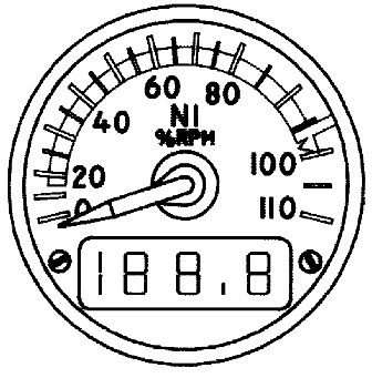
We are very fortunate to have a document that provides the tachometer pin numbers, so we know where to connect power and the tach signal. What we don't know is how closely the tach signal must match the MIL-G-26611 definition. If the tachometer will operate with a simplified signal, interfacing will be easier and cheaper.
MIL-G-26611 describes an old style tachometer generator. Although it's called a generator, electrically it's actually a alternator that produces three-phase AC voltage. Its electrical output was originally used to power a small three-phase permanent magnet motor inside the old style tachometer. The motor shaft spun a drag cup mechanism that deflected the gauge needle. The drag cup mechanism is essentially the same as the insides of automotive speedometers of the 1950s and 60s.
So, from MIL-G-26611 we know that the electrical tachometer generator signal is a three-phase sinusoidal AC voltage that varies from 0 to 21 volts and 0 to 70 Hz as the shaft RPM goes from 0 to 4200. From the tachometer documentation , we know that the gauge we want to interface only needs a single-phase input, that it will respond to a signal as low as half a volt, and that it does substantial filtering of the input signal.
The tachometer most probably uses only the frequency of the input signal to determine engine RPM. Although the voltage varies with RPM, it isn't spec'd do so accurately. Frequency, however, is rigidly controlled by engine RPM. As long as voltage is high enough, frequency can be used to precisely determine RPM.
The fact that the tachometer filters the input signal implies that we don't necessarily need a clean sine wave. Aircraft might have all kinds of electrical noise in its systems. Long cables like those used to connect engine sensors to cockpit gauges make good antennas for electrical hash. The tachometer signal might start out as a sinusoid, but what the tachometer sees can be something else entirely. Filtering is an accepted way of life.
Putting these facts together suggests that we might be able to drive the tachometer by varying the frequency of a fixed amplitude square wave.
Two important questions come to mind. Does the input signal have to cross over 0 volt? How much power does the input require?
The MIL-G-26611 tachometer signal is an AC voltage that swings both positive and negative. We can make a signal like that, but a signal that swings between zero and a positive voltage is trivial. Trivial is to be desired, because trivial means cheap and easy.
A MIL-G-26611 old style tachometer sucks down a moderate amount of power, at least in today's instrumentation terms, because it's running a little electric motor. The newer gauge we're investigating doesn't need the power to operate, but it might present a low impedance to reduce susceptibility to induced electrical noise on the signal cable. A low impedance would require more power to drive a workable signal into the gauge.
Since we can't find these answers in the documents we have, we (read "Rob") will make some experimental measurements using this simple oscillator.

The oscillator produces a 30Hz square wave that swings between 0 and 5 volts. If connecting the tachometer to connection A results in the tachometer displaying 2100 RPM or thereabouts, it's happy beer time. If it doesn't, but there's no smoke, there's no cause for dismay. We're not in this for the money, after all.
If connection A successfully drives the tachometer, we know the signal doesn't have to swing below 0. If not, we'll modify the oscillator and try again.
Regardless of whether or not the tachometer responds to the A signal, we (once again, "Rob") will connect the tachometer to B and measure the voltage at the tachometer input then repeat the process at C. These measurements will allow us to calculate how much power the tachometer requires at the signal input.
Once we have these answers we can plan more tests or move on to looking at interface options.
Still Here (4 December 2009)
Done with the flu, car still misbehaves, new water heater, little flight sim, roof still tight.
Still Here (18 November 2009)
Flu, misbehaving car, leaking water heater, not much flight sim, at least the roof doesn't leak.
Photometry (24 September 2009)
Photometry is the measurement of visible light. Specifically, it's light that is visible to the human eye. When we use photometry we are using a set of measurement tools which incorporate a weighting curve based on the sensitivity of the human eye. When we want to design lighting systems for buildings (at least those occupied by humans), we turn to the tools of photometry. When we want to document the performance of displays and projectors, we turn to photometry as well. When we want to market displays and projectors, we use some of the words of photometry...
Imagine the plight of a hypothetical individual who wants to gain an understanding of the science behind arbitrary display systems. There are many steps between light source and eye. Getting a handle on what makes a display excellent, or merely adequate, requires understanding all those steps. The information is out there, but it's a mix of hard science, professional lore, and marketing hype. Pulling it together is a challenge.
Embarrassing BRFS Error (17 September 2009)
Gene has done an evil thing. He emailed me about an error in Building Recreational Flight Simulators before I'd had my first cup of coffee. Seems the pivot hole in the throttle arm is incorrectly dimensioned with a diameter of 5/8" in figure 12 on page 136. The correct diameter is 3/8". Not having adequate caffeine in my system, this news was hard to take.
Actually, Gene's only sin is having a shop that is way cooler than mine. Check it out.
Motor Options (10 September 2009)
I added source info to the BRFS support page about possible stepping motors for use in the DIY stepping motor based gauge project.
Not Much, at Least Not on the Sim Front (1 September 2009)
Getting kids into and out of apartments, watching the dog and cat, random honey-do house projects,...
Read Robert Sawyer's latest, Wake: Enjoyable, readable, a very intricately engineered plot that's fun to deconstruct. I'm waiting for the rest of this trilogy.
More Circuit Boards for BRFS Projects (21 August 2009)
I've added a few more design files to the BRFS Support page.
Circuit Boards for BRFS Projects (20 August 2009)
I don't sell them.
But, I know where you can buy them.
I started making PC boards for the BRFS projects at home using the toner transfer method, nasty etchant, and carbide drill bits. When I noticed that people on the forums who were making boards were preferentially using professional board houses, I switched. I chose ExpressPCB and have been pleased with the results.
ExpressPCB provides free board design software, and you price and order the board over the Internet using the design software menu and that insidious bit of plastic, your credit card.
I've just started posting the board design files for the BRFS projects on the newly created BRFS Support page.
It'll take me awhile to get all the files posted, but eventually I'll post the hex micro controller files and what ExpressPCB board files I have. (Not all boards were prototyped professionally.)
Book Reviews (13 August 2009)
Well, Building Recreational Flight Simulators has been out long enough for a few industrious souls to review it or comment on it.
Trevor Hale reviews it at MyCockpit.
John "jmig" comments on it at MyCockpit.
"Ruprecht" reviews it on his pitblog.
My thanks to them for their efforts.
Random Stuff (6 August 2009)
Well, there isn't much important to say flight sim wise. I'm caught up on shipping books. Most go out within a business day of receiving the order. If the order comes in by 8AM, the book just might get shipped that day. I still can't get the van in the garage; I've yet to stack the book cartons out of the way.
I've given some serious thought to Book 3. I've collected a pile of source material and done a goodly amount of outlining. Have to sit on it for awhile and see what hatches.
The roof is almost done. A few mostly cosmetic details remain, but the beast is weather tight. On to the next honey-do...
Book Orders (30 July 2009)
All book orders up to 3PM Pacific Time, 30 July have been shipped. Normally, I would send an email as each order is fulfilled, but I can't keep up with the volume. I figured it was more important to get the books in the mail ASAP.
Normal delivery times for US addresses is 2~3 business days. Non-US addresses take 4~6 business days PLUS the time for local delivery and any customs interest. Very occasionally non-US deliveries will take much longer (like 6 weeks!), but this is rare. If there is a problem email me and we'll find a solution.
Once again, thank you.
Wow! (29 July 2009)
Spent half the evening last night and a couple hours this morning packaging books and filling out customs forms.
Thanks!
(Got to go work on the roof for awhile now.)
They're Here (28 July 2009)

You can place an order on the Book 2 Information Page.
Book Delivery (27 July 2009)
The trucking company called this morning and said the truck will be here between 1 and 5 PM Tuesday. I will turn on the PayPal ordering buttons once the books are here.
Building Recreational Flight Simulators (26 July 2009)
With luck I'll have the books early next week.
I've added a two chapter sample to the Book 2 information page.
BRFS Production (22 July 2009)
Yesterday I received a letter from the city saying the sewer lines in my street will be replaced. Today I received an email from Thomson-Shore saying the books have been shipped.
Will the truck arrive before the road goes?
The race is on.
BRFS Production (20 July 2009)
Received the invoice for the outstanding balance for producing Building Recreational Flight Simulators. The check is in the mail. The books may be shipped as early as the 22nd. This is slightly earlier than I expected. There will now be a marathon cleaning session as I excavate a hole in the garage stuff so there is a place to store them. Hopefully there will be no need to store them for any length of time. Hint, hint.
Roofing (18 July 2009)
Little by little.
BRFS Production (13 July 2009)
Thomson-Shore tells me they are currently shipping within 11 days of approval of proofs. Once time is added for final payment to reach them, and for the truck to reach me, that makes delivery look like early August.
A small glimmer in a day filled with roofing stuff.
BRFS Production (10 July 2009)
I received the proofs for Building Recreational Flight Simulators yesterday, reviewed them, and emailed approval to proceed. I got an email letting me know the book has been released to production.
On the home front, the roof repairs are moving along a bit slower. Holy Cow, is that stuff HEAVY!
BRFS Production (7 July 2009)
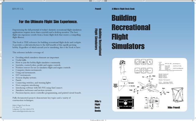
I've been on the phone and exchanging email with the people at Thomson Shore resolving issues with the cover file. I had prepared the cover artwork using CMYK color space as required by commercial presses, and I naively thought the process of creating a PDF file would result in a file with CMYK colors.
Silly me. The PDF conversion encoded all the colors as RGB.
So I got an email asking for a CMYK file.
Okay. No prob... sort of.
Two hours of arm wrestling, and I've got a CMYK file which I email back.
Next email: Yes, it's CMYK, but we really need to be able to pull a single separation for the background color. You've spread it across a couple. And, you've got a font that's no longer embedding properly. Oh, it looks like you have an image at too low a resolution.
????
Fortunately the email also had the phone number of a technical wizard. After some very patient handholding, the issues were resolved, the new files emailed, and BRFS is back in the production stream.
BRFS Production (1 July 2009)
I spoke with one of the production people yesterday. They're reviewing the files I sent. (What precise color blue do you want for the cover?) There is no firm ship date as yet. They'll review the files, wait for any needed corrections from me, make the plates, and schedule press time.
So far, so good.
If you're interested in the book production process, take a browse through the Thomson-Shore website. These are the people who are producing my book.
Building Recreational Flight Simulators is Complete (25 June 2009)
The production files for Building Recreational Flight Simulators and its cover are complete and have been burned to a CD. I could have FTP'ed them, but I had to send some paper (signed contract, etc.) anyway, so I just stuffed it all in a single, snail mail package. Currently, production is running about four weeks from receipt of order. Once the books are in cartons, it's another week or ten days for the delivery truck to meander from the production facility to here. That puts us into the first or second week of August before I can start shipping book orders. I won't be accepting money until I have product in hand to ship. Gives me time to work on the roof.
Book 2 Progress (23 June 2009)
I continue to find mistakes in my "production ready" manuscript file. They are small, but as annoying as the ones I don't find will be embarrassing. Most are inconsistent formatting issues. A few had to do with non-sequential numbering of the illustration captions. The worst, so far, was a footnote reference to an appendix that didn't make the final cut. I don't know if I should be pleased or frightened that I'm not finding any technical content errors. (Airspeed's still measured in furlongs per fortnight, isn't it?)
I got the production quote updated, but haven't been able to get them on the phone since to kick off the start sequence. Email tonight, and phone tomorrow, I guess.
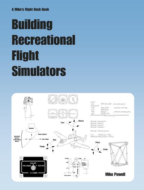
Here's the check plot for the cover. It matches the style of book 1 and should be up to holding the pages of book 2 together.
Book 2 Progress (21 June 2009)
I now have a production ready manuscript file in PDF.
Next steps: more checking, second guessing myself, and finishing the cover.
Another possibility:
PITA Book Production Details (19 June 2009)
Checking the parts lists, adding specific manufacturer item numbers where there might be confusion, etc. Time consuming. Sigh.
It appears that my copy of Adobe Acrobat is so old it doesn't quite do what it's supposed to. I suspect the automatic Acrobat Reader updates have confused it. My old copy works well enough for making PDF docs that print on 8.5 by 11 paper at home, but it's not passing the correct book page dimensions to the printer. That's okay for my little HP here, but send that file to the zillion dollar laser zapping press-plate prep machine and I've just wasted a big chunk of set-up money. Bad idea! Sigh! Solution: spend yet more money and buy a somewhat more current version of Acrobat.
Spoke with the production people about paper, among other things. They had sent me a sample of some really nice paper, thin, but with very good opacity. Sadly, it turns out to be for 8.5 by 11 printing. Yes, they can cut it down, but not economically. Or they could try to special order it in a different size, though that might cost a bit more. Finally decided to go with one of their stock papers. It's not quite so opaque, but they assure me it will work well for what I'm doing. The tradeoff (besides not blowing the budget on paper stock) is to have an opaque enough paper stock so that overleaf printing and drawings don't distract, but not have a book that's so thick that I can't mail it using the flat-rate priority mail envelopes.
And I couldn't finish the cover artwork until the paper stock was decided upon because paper thickness changes the spine width. But that's okay because I'm still toying with the cover image.
Clock's ticking. Sigh.
Book 2 Draft Front Cover (17 June 2009)
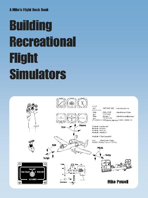
Maybe...
Book 2 Manuscript Clean Up Progress (16 June 2009)
Well, for almost three minutes I thought I was done.
Then I remembered I wanted to double check the project parts lists. Other than that, all the (known) edits are done, and even the page number on the title page is gone.
So, as of now, it looks like checking parts lists and finishing the cover are the only remaining items.
Book 2 Editing (13 June 2009)
I've completed a read-through of a print out of the manuscript. There are a lot of red marks in it now. I'm amazed and a little embarrassed how many there are. It's not like this is the first time I've read through the material, but reading hardcopy is somehow different than reading on a monitor.
I re-wrote a few paragraphs to improve clarity. There were several missing words. There were even some spelling mistakes. Spell check doesn't catch everything; it won't highlight "filed" when it's typed for "field". Most of the edits were word choice changes to make the sentence sound better.
All in all, I guess I shouldn't be too embarrassed about finding mistakes. This is the nature of writing, editing, and re-writing. The truly embarrassing mistakes will be the ones you find.
Next up is making the corrections, and printing a new hardcopy. I'll put that aside while I work on the cover then read through it again.
Editing a 608 page book is time consuming.
Book 2 Editing (8 June 2009)
It's happening. Slowly, but it is happening.
Book 2 Status (4 June 2009)
This is the check copy of Building Recreational Flight Simulators, all 608 pages of it. The only known issue is the presence of a page number on the title page. I'm sure I'll find some more once I sit down with my trusty red pen, but I think I'll leave that for later and just savor the moment.
Next big step is finishing the cover artwork.
Warning & Status Lights Chapter Project (2 June 2009)
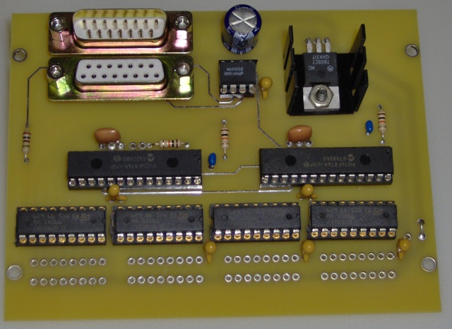
The lamp driver project from the Warning & Status Lights chapter (the circuit board pictured below) is sitting on my desk happily blinking away. This is the third version of this project, and the best. I'll make some very slight changes to the PC board artwork to accommodate some flat cable headers. Other than that, this one appears to be finished.
I revised the manuscript indexing which now looks pretty good. There is actually a bit more room for further indexing, so I'll take a look for any areas that may be a bit sparse and perhaps make a few more entries.
Book 2 Status and Project PC Board (30 May 2009)
I've completed a first pass at indexing the manuscript. A few minor formatting issues remain, easily remedied.
I'm still checking the book projects. The circuit board for the warning lights project showed up Friday. It took a little less than two hours to collect the parts and assemble it. Just need to program the PIC micro controllers and remember where the host test code is.
Book 2 Status (26 May 2009)
While waiting for the remaining project circuit board to show up, I decided to try a test build of the complete manuscript. Up til now I've been working with separate files for each chapter. Life is far easier if there's a single file for generating the table of contents and index. Thing is, it's a really big file with lots and lots of imbedded images. If you're not careful, formatting oddities that tend to accumulate throughout the individual chapter files go on the warpath when set loose in a single combined file.
Apparently I've been nearly careful enough. I had built a custom template, and attempted to use only the formatting defined in the template. When I built a test file, nothing blew up. True, the page numbers disappeared, and the table of contents default formatting needs some help. All in all, though, I call it a success.
I've still got a lot of checking to do, and tagging the index entries will be time consuming, but the end is in sight.
Completing the Tactile Transducer Amplifier (24 May 2009)
Well, it seems to work.
This is the first time I've used an LM3886T. It's the power chip on the back edge of the board. It's a 68 watt audio power amplifier. It seems quite well behaved, no spurious oscillations or grief. It just made the transducer vibrate my hand, just as it was supposed to.
The 14 pin chip in front of the power amp is a quad opamp configured as a low pass filter. It attenuates everything above 50 hertz. No point sending high frequencies to the amp if you can't feel them. They just cause excess heating.

The only issues I had building this were related to hole sizes. I had to drill the holes for the power amp slightly larger, and the board mounting holes were way too small. No signal problems what so ever.
Lest you're wondering, the picture does not show the absolutely required heat sink for the LM3886, because I used a clunky, non-photogenic one during testing.
Project Checking (21 May 2009)
Having set down to build the tactile transducer amp, I found that I did not actually having all the parts. Since I had placed two orders to make sure I did, I find this rather annoying. About all I have to show for my efforts is a picture of an unfinished project.

The Illustrations for Book 2 Are Done (16 May 2009)
Which is not say that they are completely finished. I still may tweak or improve them, but there are no gapping holes where a drawing should be. I'm now officially into the checking and editing phase.
I've finally got a hardcopy with no holes or red marks. That'll change.
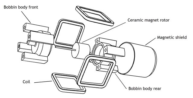
And Another Illustration Done (13 May 2009)
This is from the DIY Instruments chapter. It's an exploded view of a commercial air core movement.
Another Illustration Done (12 May 2009)
One more illustration is done, along with some line editing.
The tactile amp boards are here along with all the parts. Just got to build and test. It'll all work perfectly the first time, right?
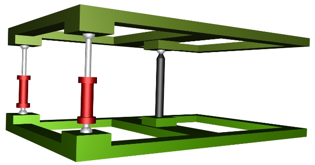
Another Illustration Study (7 May 2009)
This is a 3D study or sketch for one of the remaining PITA illustrations. The final illustration will be a line drawing.
Working on Illustrations, etc. (6 May 2009)
Have made some inroads on the remaining illustrations. The circuit boards for the tactile transducer amp showed up, right on schedule. Unfortunately, the parts did not. I suspect that my not placing the order until after the boards arrived may be the cause of that.

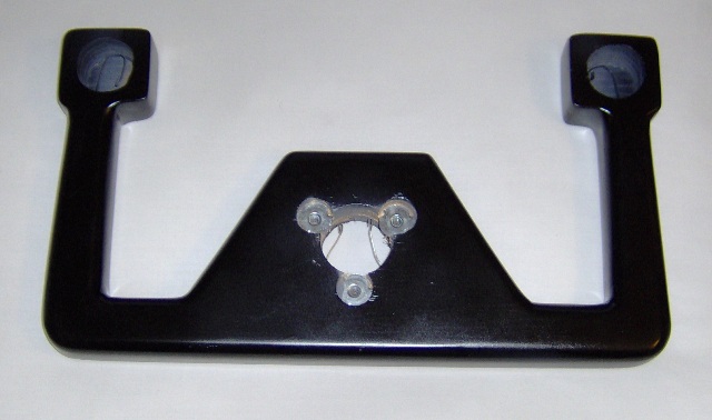
Joystick Hall Sensor and Magnet Assembly (5 May 2009)
This is the implementation of the joystick position sensing. There is an Allegro A1301 linear Hall sensor (the little black thing with three leads) which is stuffed inside a piece of brass hobby tubing. The tubing has a brass washer epoxied to one end. This forms a flange used to hold the tubing in position inside the joystick mechanism. The magnet assembly consists of a pair of ceramic disk magnets inside a short length of 1" steel electrical conduit. The magnet assembly moves as the joystick moves. The sensor is stationary. The sensor voltage output varies as the cosine of the magnetic field angle. Since the joystick only moves through a small arc, the voltage output is actually linear within a few percent.

There are two sensors and two magnet assemblies; one for roll motion and the other for pitch.
The A1301 Hall sensor is powered by 5 volts and produces an output that ranges between about 0.1 and 4.9 volts. So, while the A1301 is most definitely not a potentiometer, it can sometimes be directly substituted for one. If the potentiometer is wired as a voltage divider between 5 volts and ground, the wiper voltage will vary between 0 and 5 volts. A circuit configured to use a potentiometer in this manner is a good candidate for a Hall sensor substitution. This is frequently how potentiometers are used in game controllers. There are no guarantees of success, but if you're adventurous, a game controller and a Hall sensor can be a fun bit of hardware hacking.
More Editing and Printed Circuit Boards (4 May 2009)
I've brought the Joystick chapter up to date with the changes in the project, and done some general cleanup throughout the manuscript.
I've also been working on circuit board artwork for almost all the projects.
LED Driver Printed Circuit Board (30 April 2009)
I've been tweaking the layout of the LED driver printed circuit board artwork. There are no circuit changes, I'm just changing some of the component positions. The major change was to bolt the 7805 voltage regulator to the board. This makes it a little more robust. In this case there is enough clearance for a heat sink, so it makes sense to update the mounting this way.

My tactile transducer, an Aura AST-1B-4 bass shaker, showed up yesterday. I don't believe Aura makes that particular model any more, but that's okay. I bought it through Ebay and the price was right. I'll be driving it with the LM3886 amplifier project mentioned below. I ordered board prototypes this morning and should have them by the middle of next week. I suppose I should take the time to collect the parts and order the ones I don't yet have.
Watching Paint Dry (28 April 2009)
Okay, it's not quite that bad. I've been drinking coffee, too.
To make the joystick project a bit more photogenic, I've been painting it. While the paint dries, I've been working through other odds and ends, virtually anything to avoid the PITA illustrations.
Currently I'm putting the finishing touches on the artwork for an amplifier for a tactile transducer. This is a minor project near the end of the book. It uses an LM3886 single chip power amp. I've incorporated a low pass filter on the board. There's no point in sending other than the low-low frequencies to the transducer.
Editing (23 April 2009)
Eye-crossingly large amounts of line editing. Lots of content editing too. (rubs eyes, starts typing again)
I haven't quite finished the joystick project. While waiting for an opportunity to get a few more parts, I started cleaning up the accumulation of red editing marks throughout the manuscript. I now actually have a relatively complete manuscript. About half a dozen pain-in-the-ass illustrations are missing. They're PITA illustrations BECAUSE they're missing (and because I'm not looking forward to creating them).
Joystick Project (12 April 2009)
Found a problem with the optional control loading springs, so I'm rebuilding a portion of the re-re-designed base.
Joystick Project (5 April 2009)
Slowly assembling the project for the Joysticks chapter. Got side tracked by a sale at a homebuilding supplies store. Part of the roof is at the end of its life; just can't patch it any more. There was a 25% off sale for shingles, plus a $100 gift card for purchases totaling more than $400. Couldn't pass that one by. But, man is that stuff heavy! It took two trips, and my back still aches. Hope to get the manuscript off the printer before roof fixin' weather shows up.
Magnet Assembly Evolution (25 March 2009)
The joystick chapter project uses linear Hall effect sensors as part of the position sensors. The project configures the sensors so they respond to changes in the angle of the magnetic field that "illuminates" them. The magnetic field comes from magnet assemblies mounted on moving parts of the joystick.
The magnet assembly should produce a field that is uniform over a large enough volume so that construction tolerances for the rest of the project can be relaxed. The magnetic field should be more or less contained. We don't want stray field components interfering with other Hall sensors. The converse is true as well. The assembly should provide shielding so that the Hall sensor is not influenced by external fields. And, it would be nice if the assembly were cheap and easy to make.
I've gone through several iterations developing an "optimal" design. Here's how the design evolved.

The proof of concept design is at the top left. The steel angle brackets both secure the two ceramic magnets, and also provide the magnetic back circuit to contain (most) of the field that is not in the gap between the two magnets. The field strength can be changed by varying the number of washers between the two brackets; a wider gap between the magnets results in a weaker field.
The top middle design is what I thought I'd use in the book. It's made of 3/4" steel angle and uses larger diameter magnets. This gives a larger volume of uniform field strength. The use of angle makes it easy to mount the assemble wherever it's needed. Trouble was, I was seeing too much magnetic leakage.
The design at the upper right was a test of reducing leakage. It's an improvement, but requires bending a 3/4" by 3/32" piece of steel bar. It's doable, but a hassle.
The lower left approach aims to be a bit easier to make. It's cut out of a single piece of 20 gauge galvanized steel. (It started as a 2" by 5" nail plate used for splicing wood framing.) It's easier to build, but is too thin to adequately contain the magnetic flux. It works, but is too "leaky".
The lower middle design uses 16 gauge steel. Magnetically, it works much better. The 16 gauge steel was cut from a nail stop I picked up at Home Depot. The mounting ears are a lighter gauge steel epoxied in place. It's not a bad approach, but there is still some leakage (fringing) from the open end. Plus, you've got to bend a relatively thick piece of steel. It's not as bad a bending the 3/32" bar, but could be easier.
The lower right design is the best so far, and is most likely what will go into the book. It's short length of 1" thin wall electrical conduit. The magnets sit on small squares of 16 gauge steel epoxied to the inside of the conduit. The mounting ears are epoxied to the outside. This design has very good shielding, low leakage, and the thin gauge mounting ears are easy to bend. The field strength can be adjusted by placing steel shims under or on top of the magnets to change to gap length.
Joystick Project (24 March 2009)
Between reading some Charles Stross science fiction (Iron Sunrise, and Singularity Sky), and watching the economy trash my retirement fund, I've also been building the project described in the Joystick chapter. This is, I think, the third incarnation of the joystick project. (So far my retirement fund has yet to achieve it's first re-incarnation.) The big change in the project is a shift to using Hall effect sensors. These are not the expensive rotary Hall position sensors. Rather, I'm using inexpensive linear Hall sensors (Allegro A-1301). Because the sensors respond only to the magnetic flux that is normal (at a right angle) to the surface, I simply use the joystick motion to rotate the magnetic field surrounding the sensor. The output voltage is proportional to the cosine of the angle. This would seem to be too nonlinear to be useful; however, the angular motion of the joystick isn't large. Within its range it's surprisingly linear. The magnetic field comes from a few cheap ceramic magnets and a few bits of mild steel.
Cheap Hall sensor plus cheap magnets plus steel bits equals neat joystick.
Of course, I can never seem to leave well enough alone. So, I've been playing with different ways to build the magnet assembly. The first version used a couple of chunks of 3/4" steel angle. It looked kind of over built. I think I'm now on the fourth revision. It's based on a U-shaped piece of 16-gauge steel cut from a nail stop. (Nail stops are metal plates used in home construction to prevent nailing through drywall into hidden wiring. A nail stop is a cheap source of small quantities of steel steel.) I'm also thinking about using a short length of galvanized conduit. That would be revision five.
The advantages of using conduit is that it's used for the joystick shaft, and that the geometry would provide slightly better magnetic shielding. Hmmm, might give it a try.
I suppose at some point I need to just call it good and publish the damn book.
Load Cells (14 March 2009)
Having completed another editing pass through the Control Yoke chapter, I freed up two pages. I also had two pages that got loose from somewhere else. I used this space to fit in a four page section on load cells and strain gages into the the Position Sensors chapter (which is now the Position and Force Sensors chapter). Here's one of several illustrations from that section.
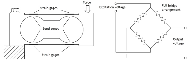
Four pages are not really enough to do justice to the topic; however, they are enough to present a good introduction. Force activated controls aren't widely seen in the sim world, but they do pop up now and then. Having a rough idea of how force sensors operate seems to me to be a good thing. This section provides just this level of knowledge, and points to a few sources of in-depth information.
Control Yoke Chapter (8 March 2009)
I have updated the project drawings for the chapter. I'm now making an editing pass.
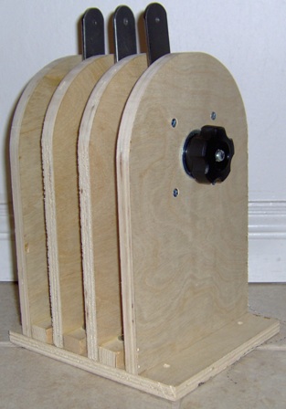
Control Yoke Chapter Project Prototype (19 Feb 2009)
The yoke has one color coat on it. It's a semi-gloss black which looks nice except for the fact that it highlights all my finishing imperfections. Matte black would be a better choice to disguise my mistakes. I'll spray a few more coats over the next few days.
There will be a solid cover over the center and smaller covers over the holes in the yoke horns. These smaller covers will support switches. I may put a trim switch in one and a PTT switch in the other.
This pretty much completes the project. Most of my effort will go into updating project drawings and chapter editing.
Control Yoke Chapter Project Prototype (14 Feb 2009)
The yoke has gone through two rounds of adding polyester filler and sanding, followed by a coat of grey primer which clearly indicated the need for a third round of adding filler and more sanding. I'll give the primer until tomorrow to dry more fully, then add a few spots of filler, to be followed by sanding and more primer. Seems to be a pattern here.
Control Yoke Chapter Project Prototype (12 Feb 2009)
I'm down to the finishing details which promise to be dusty. The glue has dried on the yoke grip. Now it's time to contour, fill, and finish. The picture shows the plywood glue-up after some clean up. I've removed the bulk of the glue blobs and smoothed the edges. I'll use a router with a round-over bit and finish with a wood rasp and sandpaper. The plywood is quite porous. To get the smooth paint finish I want, I'll use polyester filler to fill the wood grain.

This is not the most artistically inspired yoke, but it serves to demonstrate what can be accomplished with inexpensive materials.
Control Yoke Chapter Project Prototype (10 Feb 2009)
The control yoke project is coming together. As with the other projects in the book, this project is a demonstrator. It's meant to answer a number of recurring questions. For example: How do I get a solid feel in a mechanism that must both rotate and slide back and forth? Use industrial flange (or pillow block) mounted bearings and heavy-duty drawer slides. How do I get smooth control loading without welding to the control tube? Wrap flexible steel cable around the control tube. Connect the cable to springs. The cable will grab the control tube without slipping. How do I physically connect the potentiometer to the yoke roll motion? Use heavy woven fishing line. A tension spring keeps the line taught so there is no backlash. An idler pulley minimizes the lateral force on the potentiometer shaft for long life. By choosing the correct diameter for the potentiometer knob you can get full rotation of the pot with only 180 degree rotation of the yoke.
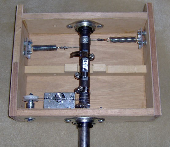
The yoke grip will be built up from layers of plywood. This allows inclusion of wiring channels for switches in the yoke grip horns. That part of the project is currently waiting for glue to dry.
Control Yokes Chapter Project (5 Feb 2009)
Steady progress on the chapter project. Most of the behind-the-panel bits and pieces have been made. I hope to start on a very basic yoke which will be built up from plywood layers. It will have internal wiring channels and options for switches in the top of both horns.
Engine Controls Chapter (3 February 2009)
I have revised the Engine Controls chapter to reflect the changes to the chapter project. At this point the chapter is in pretty good shape. I'm missing one illustration, and trying to decide if it will add enough to warrant the effort to create it. While I ponder that weighty question, I've started building the prototype of the Control Yokes chapter project.
Revised Throttle Project (30 January 2009)
The project revisions are an improvement. I replaced the T-shaped rocker arm with a simple pulley. Cost is about the same. Materials are easier to locate. Assembly time is reduced. I choose projects specifically to illustrate different approaches, and I've already used the pulley technique in another project. However, there seems to be no value in holding on to the rocker arm.

Throttle Project (25 January 2009)
The throttle quadrant project from the Engine Control chapter is together and it works as it's supposed to. So, naturally, it's time to make some changes. After all, just because it works doesn't mean it's good enough.
This is a demonstrator project. The intent is to illustrate techniques. I leave it up to the reader to adapt those techniques to a specific aircraft model. The project shows how to provide adjustable friction to lever movement, how to reduce mechanical play, how to maximize the lifetime of a slide potentiometer, and how to incorporate the strength of metal parts without resorting to welding.
My next step is to simplify the construction a bit.
Still Building the Throttle Project (22 January 2009)
Getting closer.
Building Projects (15 January 2009)
I'm building the throttle project from the Engine Controls chapter. Not much to show as yet.
Still Here (3 January 2009)