
Book 3, Chapter 2 (31 December 2011)
This is the background chapter which defines a working vocabulary of light, explains how display system performance is measured, and describes what we need from a display system if we're to perceive a high quality image.
I wrote the first draft quite some time ago. Since then I've worked through the rest of the book and gained a new understanding of what background should be included. So, naturally, this effort has turned into a massive revisioning exercise.
So, more research, more examples, more illustrations, and I'm not done yet.
Mike's Tips Article & Chapter 2 (20 December 2011)
I finished an article on display characterisitcs which improve immersion. It's now posted as a Mike's Tips article over at MyCockpit.
I'm in the middle of revising chapter 2 of book 3. Chapter 2 provides background for developing game display systems. It defines important photometry terms, explains how to use and abuse them, then finally overviews human vision. The idea is that if you're going to design a large display system you should be able to extract meaningful data from sales literature, and choose equipment which provides cost effective performance.
Book 3, Chapter 1 (8 December 2011)
Okay! Finally... a first chapter revision that works.
Book 3 on Display Systems & Immersion (4 December 2011)
I've been occupying myself with revisions to the book 3 manuscript. Actually, revisions is a poor word for it. I nuked the first chapter. Even the title's been changed, several times, in fact.
Book 3 is about display systems for computer games. It's not just concerned with projector set up or LCD selection, though there's that and more. It's about crafting a display system that allows you to get lost in the game application. It's about immersion.
The first chapter has to put all the nuts-and-bolts detail of later chapters into context so the system designer knows what leads to immersion and what doesn't. The key concept is deceptively simple: emulate the real world visual experience. Chapter 1 expands on that concept.
Mike's Tips, the A-10C MIP, & Book 3 (22 November 2011)
I fired off another edition of Mike's Tips which should be posted on the MyCockpit site sometime in the next few days. This month it's a overview of how to make a main instrument panel for contemporary fighter aircraft sims. This type of aircraft tends to have complex MIPs that do not lend themselves well to simply cutting holes in flat panels. I used the A-10C MIP project as an example.
And speaking of the A-10C MIP, I'm moving this project toward the back burner. I'll still be working on it, but more slowly. It's been occupying most of my time and there are other projects needing attention.
Book 3, Building Simulator Display Systems, has, in fact, been on the back burner. I haven't made significant progress on the manuscript for longer than I like to admit. The bulk of the material is there, but there's a lot to be done. There're the obvious holes which need to be filled, but a bigger issue is that the high level structure feels a bit lame. There's a lot of really good material, but it's a bit overwhelming. The structure should provide more guidance in navigating through and choosing among the mountains of facts.
A reader shouldn't need to undertand the whole book to decide which portion to apply to a specific project. For example, you shouldn't need to slog through the details of projection screen gain to decide that three LCD monitors are the best choice for your particular application.
What this amounts to is a need for better introductory material for chapters and major sections. There needs to be more when and why before diving into the what and how.
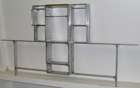
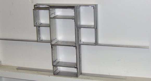
A-10C MIP Project Progress (17 November 2011)
I have all the bar pieces in place. There are a few more corner gussets to add, and I've yet to put any of the threaded spacers in the corners. Here are two pictures of the current structure:


Although the epoxy bond with aluminum can be very strong, its strength depends greatly on how the aluminum surfaces are prepared. I managed to break some and judging by the lack of scratch marks, the weakness was due to having not sanded the gluing areas. Bottom line: to assure strong glue bonds, aggressively clean the gluing surfaces with 100 grit sandpaper.
I have a few minor tweaks and a lot of clean up to do. I'll then move on to adding some sheet aluminum. Some is glued on permanently while other portions will be mounted with screws.
I'm planning on cutting the backing plates for the sub-panels and using them to hold the threaded spacers while the epoxy sets up.
At this point I have about $70 in materials in the project. That's for the bar aluminum, the angles used to gusset the corners and a lot of epoxy. The threaded spacers will add about $40, while the sheet metal will add another $30 or so. These figures include the shipping costs associated with ordering the material.
I haven't kept track of the time I've worked on this. I don't think that's really important. The process of working on a sim is a payout for me. I think it's a real hoot to see something like this take shape.
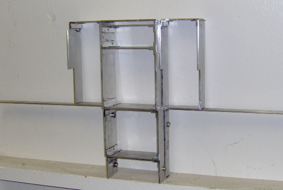
A-10C MIP Project Progress (10 November 2011)
I added the first bent piece to the structure. I formed the bar over a coupler for 2" diameter rigid conduit. The spring back of the aluminum bar gave me a bend radius close to the desired 2".

The next piece has a lot of bends.
A-10C MIP Project Progress (7 November 2011)

The next two pieces have some bends in them. Being .125" thick, the aluminum bar doesn't cooperate well when it's time to bend. I made a rough bend on a scrap piece using a vice and a hammer. To get the bend I want, I'll need something to bend the bar around. Time for a trip to the store.
A-10C MIP Project Progress (6 November 2011)

A-1oC MIP Project Progress (5 November 2011)
A-10C MIP Project Progress (4 November 2011)
A bit farther along.
A-1oC MIP Project Progress (1 November 2011)
It's beginning to look promising.
A-10C MIP Assembly (29 October 2011)
Even using fast setting epoxy this is slow going. Perhaps once the center section is together and stable I can add several items at a time. Currently I have to add items one by one. Any misalignment at this point will screw up everything done later.

A-10C MIP Parts (26 October 2011)
I have all the difficult parts cut. There are two of most of these parts. When epoxied together, these will in theory form an extremely realistic A-10C main instrument panel structure.

The wide black marks are not the cut marks. (I'm a little more sophisticated than that.) I use a wide black marker in place of marking dye. The actual cut line is scribed in the darkened area and is very narrow. The black marker boosts the contrast so I can see the line.
There are a number of short lengths of aluminum angle remaining to be cut which will strengthen the corner joints.
With luck, I'll start assembling tomorrow.
Cutting Metal for the A-10C MIP (25 October 2011)
I now have most of the metal cut for the A-10C MIP structure. There are five pieces which need more attention after which I should be able to dry fit all but the curved outer most pieces.
New Mike's Tips Article (22 October 2011)
I finished a new "Mike's Tips" article on control loading for MyCockpit, and sent it off. It should be posted within the next few days.
So Many Interesting Things (16 October 2011)
There are so many, many interesting things to do and read about, more than enough to over shadow the active to-do list...
Take CNC, for example. I don't have one (sadly) though I'd certainly like to. I'd wondered why I hadn't seen more Arduino based CNC projects. Much of what I've read about uses stepping motor drivers which are controlled directly from a PC parallel port. This is a "workable" solution, but hardly optimal. Depending on the operating system there can be some real timing issues with the parallel port signals. I finally ran across some CNC projects that used an Arduino to control the motors.
And then I ran across the grblShield. This is a three-axis motor control board which is compatible with the Uno and Duemilanove Arduino boards. WOW! And then there's Grbl, an open source Arduino app which speaks G code. WOW, again!
So, why haven't I dropped everything to start building a CNC? Is it self-control, iron willed discipline? Or, did I perhaps get distracted by something else? Did someone mention laser engravers and cutters?
Ebay lists some really cheap, desktop laser engravers/cutters. Interpret "cheap" in all senses of the word: low cost, poor quality control, questionable design,... Apparently there are a few vendors who stand behind their product, but many who do not. If you know what you're doing buying one of these units can be the start of what will essentially become a DIY project; you'll rebuild the unit by the time you're happy with, or at least accepting of, its performance.
Some have decided to just go right into the DIY mode, purchasing the laser tube and power supply then building the mechanical structure and motion control system themselves. This looks very attractive, especially so given the availability of the grblShield.
But what I've actually been working on is the roof.
We've had a chunk of roof crying for attention for some time. This spring I started the repair process, removing the damaged material only as fast as I could easily get rid of it. I took my time, because, hey, it doesn't rain here in the summer. Then fall happened, the weather changed, and the roof suddenly demanded rather more immediate attention.
With the roof taken care of, the to-do list can become active again. Sadly, CNC and lasers are not on it, but the material for the A-10C MIP arrived last week.
A-10C MIP Material Ordered (1 October 2011)
I ordered the aluminum bar and angle for the panel structure. After a bit of price shopping I went with Online Metals. I was surprised at the price difference. Even considering the shipping cost, this was far cheaper than buying through a local home building supply.
I have yet to buy the threaded spacers, and I should probably stock up on epoxy and spare hacksaw blades.
A-10C MIP Structure Proof of Concept Test (25 September 2011)
I built a proof of concept test item for the aluminum and epoxy instrument panel idea. It's two cells of the lattice structure made from 0.125" by 1" aluminum bar I bought at a local home builder's store. The concept works well and I expect it will scale up nicely.
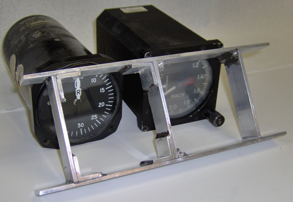
Both openings are for nominal 3.25" instruments. The opening on the right is for a square body instrument while the one on the left is for a round body. The two body types have different mounting hole placements.

The mounting holes for the square body instrument are so close to the corner that I had to slightly modify the threaded spacers to get them to fit. I'd hoped to find some spacers with a 0.187" diameter and an 8-32 thread, but no such luck. I can either file flats on the outside of the available 0.25" diameter spacers or use a round file to open up the corners in the structure. It's easier to file the spacers.
The mounting holes on the round body instrument are closer to the center and leave enough room to place a piece of 0.125" by 0.75" by 0.75" aluminum angle in the corner. This significantly strengthens the structure.
Most of the mounting holes for instruments and sub-panels on the A-10C MIP are far enough from the corner to allow the use of 0.0625" by 0.50" by 0.50" aluminum angle. This angle can also be used with the square body instruments as long as it is trimmed to clear the already tight threaded spacers.
I can't break this test piece bare handed, though I think I could bend it enough to get an epoxy joint to fail by jumping on it. In any case, I'm pleased with the approach and think it will work well for making an extremely realistic appearing main instrument panel.
Unfortunately, I haven't found any 3" wide aluminum bar on the local desert island. Looks like I may have to get a signal fire going and see if the Onlinemetals tribe a few islands over is interested in bartering.
A-10C Instrument Panel (21 September 2011)
One of the issues with aircraft instrument panels is strength. Once holes are made for the instruments, there's a lot less material left to hold things together. Look behind the sheet metal in general aviation panels and you'll find stiffeners. The situation gets a lot more demanding in war planes, and the A-10C is good example how demanding things can get.
The main instrument panel in an A-10C is so full of instrumentation that there doesn't seem to be any room left for the panel that supposed to support them. The designers met the strength requirements with a lattice structure that is almost three inches thick in some places. It's still mostly a collection of holes that hold instrumentation, but what material remains forms metal bars of considerable strength.
As far as I know the panel structure is a single piece of metal. It may have been machined from a casting, or perhaps even from a single slab. (Hey, it was a government contract.) In any case, the fabrication approach taken for the real aircraft is unlikely to be available to the hobbyist.
It occurred to me that since the lattice looks like it's made from bars, perhaps a simulator panel structure could be assembled from bars. Further, while welding would be nice, the lattice is thick enough that epoxy might provide adequate strength. I've used epoxy to good effect in other metal structures. This could be another.
I started with a collection of photographs, the user's guide for DCS: A10C Warthog, and the cockpit builder threads on the Eagle support forum. From the forum I found a set of panel dimensions for the A-10A model, and the military designations for many of the instruments. That led to some military standards that contained actual instrument case dimensions and the required panel cutouts. Several days later I had a drawing that incorporated that information.

The intent isn't to make a panel which is exact in every dimension. The intent is to make a panel which honors the actual dimensions where practical, and adapts where necessary. I want the deep sense of immersion provided by the look and feel of the real panel, but I want something I can afford to build, too.
The big impracticality is finding 5 inch square displays for the Multifunction Color Displays (MFCD). The MFCDs have a 600 by 600 resolution. With the bezel in place, each MFCD is about 7.25 inches square.
A 5.7 inch (diagonal) display is simply too small. I decided to try an 8 inch display. I found a VGA style LCD monitor with 800 by 600 resolution. The active display area is a little shy of 5 inches vertically but has a surplus horizontally. I had to widen the top portion of the panel to accommodate the larger display. Fortunately the MFCDs are located on the outer edge of the panel so enlarging them doesn't displace other instruments.
I'm not sure I'll stick with the 8 inch displays, but they're part of the prototype design for the time being.
Once I had the dimensions for each of the instrument and subpanel cut outs, I started placing 0.125" bars (virtually, in TurboCAD) around each opening. In the above drawing there are orange numbers on each sub-panel and instrument. The number represents the height of the lattice for that element. Some instruments stick out closer to the pilot, and it's this dimension that causes it. It makes the project more involved, but I think this sort of detail adds realism to a sim.
With all the bars in place, TurboCAD created a 3D model of the lattice.
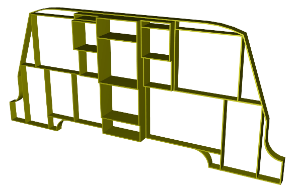
This is the basic structure that will hold everything together. What's not shown is the joint detail. Joints are not formed simply by a dab of epoxy. Each corner is effectively gusseted by large quantity of epoxy with an embedded internally threaded metal spacer.

The threaded spacer provides the means for mounting the instruments and sub-panels.
Some of the bars will be continuous and pass through notches in other bars. A few of the open areas will have aluminum sheet glued over them to provide lateral racking strength for the structure.
The next step is to build a small proof of concept model to gauge the strength.
Switec X25.168 Stepping Motor Movement (15 September 2011)
The Switech X25.168 motor is a small stepping motor with an integral 180::1 reduction gear train. The unit was designed specifically as a gauge movement for automotive use. It's used in a great many American cars and trucks for speedometers and tachometers. It runs from 5 volts and is easily controlled by a micro controller.

I bought a couple well over a year ago and have just now gotten around to hooking one up.
I used the same electronics I used for the DIY air-core movement. In fact, the electronics was designed with this in mind. The circuit board has mounting holes specifically for the Switec, but I chose to use lead wires in case I needed to hack the board during debugging. Fortunately, hacking was confined to the firmware.
I started with the firmware from the stepping motor VSI project in BRFS. I made two changes.
First of all, the Switec motor has its own stepping pattern, so I modified the stepping logic in the firmware.
Second, this particular model of the Switec has internal stops such that it will rotate only 315 degrees. These stops are used to find the zero position when the gauge is first powered up. The VSI project uses a motor without stops, so the firmware steps the motor until an optical sensor detects a flag on the motor shaft. For the Switec, which has no sensor, I modified the firmware so that it stepped the motor long enough so that I could be sure the rotor was against a stop.
The Switech provides 1/3 degree positioning which makes for smooth motion. It's a nice little unit that should work well for a range of analog instruments. They are sold on Ebay as replacement units for automotive gauges. Prices vary with quantity, and are normally in the $4~5 range each.
SMD Air-Core Movement Driver Board (11 September 2011)
I spent a little time checking communication across the serial com port link into the SMD board driving the DIY air-core movement. I have not resolved the issues of programming the com port under Win7, but I'm able to work around them via the messiness of setting the port speed manually.
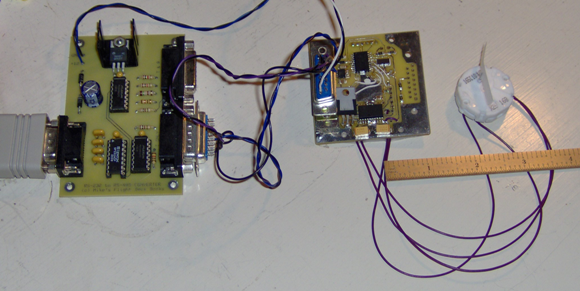
Here's the test set up.

The board on the left is an RS-232 to RS-485 adapter, (one of the projects from BRFS). The board on the right is the PIC based air-core driver. The shiny cylinder connected to it is the DIY air-core movement. It's all working now, but there were a few changes.
The first problem was some difficulty making +5 volts from +12 volts using a 7912 voltage regulator. I'm fairly certain that I used to know that doesn't work well; however, when searching for the reason for a lack of +5, I found a 7912 in place of the expected 7805. As I built up the board, it's reasonable to assume I put the 7912 on the board. Or it could have been electro-gremlins. Or maybe I just need to get my glasses replaced. In any case, the situation improved markedly when the 7912 was replaced by a 7805.
Sadly, everything did not simply begin to work properly. It ran its self test, but ignored the serial data from the PC. Happily though, it did at least it do something.
The problem was that, in order to use the serial port on the PIC, both receiving and transmitting must have dedicated pins even if the application running on the PIC only receives data. I was trying to use the I/O pin the serial port had appropriated for transmitting data. A little hacking on the board and some firmware pin reassignments took care of that.
The reason I was trying to use that pin was to keep some other pins free so they could be dedicated to in-circuit PIC programming. Since this is an SMD board and the PIC is soldered in place, in-circuit programming, which is done without removing the PIC, is really convenient. However, the pins used for programming must be suitably isolated from the circuit.
Once I completed the board hacks to get the serial com stuff working, I started having issues with the in-circuit programming. I fixed that with a bit more board hacking: I placed 1K resistors in series with the I/O pins to get the isolation needed for programming.
So, my little SMD board now looks a bit chewed up, but everything works!
DTS Revisions (7 September 2011)
Due to some interest in the Digital-to-Synchro project, I've spent a little time documenting the revisions and updating the circuit board artwork. The results of these efforts can be seen on the BRFS Support Page.
Windows 7, Com Port, and Problems Thereof (30 August 2011)
Some time back my computer rolled over and died. I took it as a sign that it was time to leave XP behind and move to Windows 7. I also moved to Visual Studio 2010 and VC++. I replaced the hard drive, but the bulk of the hardware remained the same.
I've finally gotten around to regenerating some of the software I wrote for the projects in BRFS.
Things are not going as well as I'd hoped. I program just frequently enough that I remember I no longer use Fortran and punched cards. Most everything else I forget. So, having gone through the angst of re-introducing myself to the Microsoft Visual Studio IDE, I was less than pleased to find that the code which worked a few years ago now barfs and whines.
I was even less pleased when I copied example code from the Microsoft website and it did the same thing.
According to MS docs I should be able to open the serial com port with a call to CreateFile( ), view its current configuration with GetCommState( ), modify the configuration with SetCommState( ) and SetCommTimeouts( ), and send data with WriteFile( ).
Currently I can not examine or change the configuration programmatically. My code can open the port and send data, but I must manually change the configuration by using the device manager window, and that only lets me change speed and a few other basic things. I've no idea how to change the timeout settings.
This is not just an issue with the com port. Many interesting USB devices come with drivers which expose virtual com ports. They are accessed programmatically the same way.
I need to understand why GetCommState( ), SetCommState( ), and SetCommTimeouts( ) now generate error code 1 ("ERROR_INVALID_FUNCTION") when called.
Digital-to-Synchro Project Revision (28 August 2011)
In the book BRFS there is a digital-to-synchro (DTS) converter project. It's used to create signals for driving real aircraft instruments that use synchro-style control signals.
The DTS circuitry has caused a bit of heart burn for a few builders. The source of this gastic distress is the operation of a clamp transistor that inverts the polarity of an analog signal.
Originally I used a 2N7000 switching FET, chosen for its low on resistance. The problem is that the 2N7000 does not work well when the drain is more than a few tenths of volt more negative that the source. The original thought was that the circuit would handle only small signals. In retrospect, that was a poor choice on my part. Component variation and the range of signals passed through the inverter stage differed from my prototype.
An N-channel JFET makes a better clamp. If the gate-source voltage is held at zero, the transistor acts like a low value resistor. If the gate is pulled 8 or so volts more negative than the source, the transistor turns off, acting like a very high value resistor. It's just what you want for a switch.
Almost.
One issue is that the minimum resistance of most JFETs is on the order of 100 to 200 Ohms. Something in the single digits would be better. A little shopping around found a few JFETs that fit the bill. The J108, J109, J110, PN5432, PN5433, and PN5434 are suitable.
A second issue is that while the 2N7000 is switched by the 0 to 5 volt logic level from the DTS microcontroller, N-channel JFETs require a negative voltage if they are to be switched off. Fortunately the DTS uses TL084 quad opamps and there are a few uncommitted amps available. A few resistors and the opamp changes the logic voltage to the required negative going gate voltage.
A caveat: I've bread boarded the inverter section and it works as expected. However, I have not been able to test this mod in a functioning DTS. Also, note that this mod inverts the sense of the sign bit, requiring a small firmware mod.

DIY Air-Core Movement Update (25 August 2011)
I've been testing the DIY air-core movement and the electronics that drives it. The movement seems to be working fine, and to the extent that I've tested it, so does the electronics .

As I write this the electronics is rotating the air-core shaft about once a second. I managed to lose the host test software, and since I'm too lazy to re-create it just now, I stuffed a dozen lines of self-test into the PIC firmware. Each time it completes a PWM cycle the firmware increments the rotor position. There are ten bits of precision for the position, so the rotor turns very smoothly.
This does not test the communication functions, and this is where I may have some problems. I've used the comm firmware in other projects, so that's not likely to be an issue. However, I figured I could use the pin the PIC serial port assigns to transmit data since this version of the hardware only receives data. Something I just read in the device docs indicate that might not be true. I will have to resurrect the host test code to find out.
DIY Air-Core Movement Update (22 August 2011)
I've added the field windings and the lead wires to the air-core movement prototype with the extended wire guides. It's a significant improvement which clears all known problems.

The next step is to pull something together that can spin the movement. That's intended to be the SMD circuit board I posted about last week. The hardware side of it's pretty much done. I just need to get the firmware up and running.
I'm planning on using an updated version of the firmware from the air-core VSI project in BSAI. That code was originally written for a PIC16F628 running at 12 MHz. The new hardware is a PIC16F648A running at 20 MHz. I'll have to change the timer and baud rate setups for the different clock speed. I also changed which pins are used to drive the movement, so that'll add a few more tweaks.
I hadn't had the Microchip software development tools loaded on my system for some time. The last time I had enough non-backed-up critical material on the system, it of course, rolled over and died. I had to reinstall from ground zero. At the time I didn't bother with the Microchip IDE. So now I'm trying to re-create everything, remember how to use the IDE, and not trip too badly on the changes in what is a newer version than I last used.
At this point I have the firmware partially revised. It's progressing both better and worse than I expected. Better because I have a partial conversion that assembles without error. Worse because I spent an embarrassing amount of time discovering that the bulk of my problems were due to using a header file for a 16F684 with code for a 16F648A.
I think I will create a standalone version of the firmware that simply spins the movement. The firmware is supposed to act under the control of the host PC, but I've lost all the host code as well.
DIY Air-Core Movement Update (18 August 2011)
The DIY air-core movements are working as desired. The remaining (known) issue is that the field windings aren't held in place properly. I've addressed that by reshaping the wire guides. I'm building another prototype to verify the revision. The rotor and body remain unchanged. I've lengthened the shield to match the longer wire guides and to provide protection for the rather fragile field windings.

SMD PC Boards Are Here (16 August 2011)
My prototype SMD circuit boards arrived yesterday afternoon. This is the board I will use to drive the DIY air-core movements I've been developing.

The left section is the air-core movement circuitry. The right third is board area I was paying for anyway as part of ExpressPCB's "miniboard" service. Rather than leave it blank, I put together a quickie SMD prototyping area. What might have been more useful would have been to layout an extension board with a ZIF (zero insertion force) socket for my PICkit2 in-circuit programmer. I still use through-hole PICs and a ZIF socket would make firmware development a bit faster.
This was my first foray into surface mount assembly. I used a goose neck magnifying glass and a 0.8mm soldering tip. I had a few issues with not properly cleaning the board before soldering, but overall it went together reasonably well.

I've discovered one error so far. There is a mechanical interference problem between the left connector and the voltage regulator (which isn't on the board yet). I've used a full size, through hole 7805 regulator because it optionally supplies power to the needle movement. The regulator will use the aluminum back plate (also not shown)as a heat sink.
The board can drive an air-core movement, a Switech stepping motor gauge movement, or a small generic stepping motor. The motor driver IC (on the bottom) can be supplied with 5 volts from the regulator or the 12 volts that feeds into the regulator from the left connector. The PIC micro controller (top center) has a input wired for an optional optical interrupter which allows stepping motor firmware to index the motor shaft position. Since the PIC is soldered onto the board, it's configured for in-circuit flashing using a PICkit2 from Microchip.
It just occurred to me that the board could also be used to drive four RC servos. The motor driver chip wouldn't be needed for that, but it wouldn't get in the way, either.
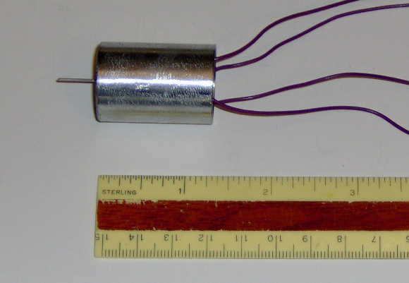
DIY Air-Core Movement Update (13 August 2011)
Here's the smaller of the two test air-core movements I've made.

It functions well. It has good torque and the rotor responds very rapidly. Put five volts on a coil and the rotor doesn't just turn, it snaps into position. I had some concern that the rotor magnet might slightly magnetize the shield and cause positional hysteresis, but I saw no indication of that. (That's still a possibility with the second test air-core movement because it has a larger rotor magnet. I haven't tested it yet.)
One shortcoming of this design is that the wire guides that hold the field windings in position don't do a very good job. They work pretty well for the first winding, but the second winding tends to slip about. I think extending the guides along the length of the movement body should cure that problem.
Of course, that means building at least one more prototype, and it looks like I may just have time to do so.
I had intended to be building my prototype SMD gauge electronics now, but UPS seems to have misplaced the circuit boards. They were supposed to have been delivered yesterday, but they were apparently not put on the delivery truck. Delivery has been "re-scheduled", but there is no new delivery date listed when I query the tracking number.
Moving into the 21st Century (12 August 2011)
I've been soldering for a long time. A very, very long time.
Sadly, my soldering gear looks like it.
Since I'm embarking on an SMD adventure, I figured I'd better upgrade my tools a bit, so I bought a temperature regulated soldering station designed with surface mount electronics in mind. I chose a Hakko FX-888.

It's a nicely engineered unit. The stand and control box both have enough weight to stay where you put them. In particular, the stand isn't in danger of tipping over when you put the soldering pencil in it. The soldering pencil is well balanced, light, and easy to hold. The cord to it is very flexible so there's no issue of the cord making it difficult to position the tip where it's needed. There is a wide variety of tips for the pencil, and they are easily replaceable. It comes with a standard size chisel tip that looks good for soldering through-hole components. I bought a 0.8mm tip expressly for surface mount work.
I'd thought that I'd find the best price on Ebay, but that wasn't the case. I got the lowest price from a firm that supplies companies with tools. Plus, they threw in shipping via Fedex for free!
So, here's a shout out for Kimco Distributing. Good selection, painless ordering, timely delivery. Thanks!
Draft PCB Layout for Stepping Motor DG (11 August 2011)
While waiting for my SMD gauge electronics PCB to arrive I pulled together a draft board design for an old project, a stepping motor directional gyroscope. This is a 3" instrument which uses a rather large stepping motor to support and spin the compass rose. The motor is serious overkill, but from a project stand point, it's a good choice, particularly so if you find the motor surplus.
Of course, this isn't exactly the same circuitry. The original project (from BSAI) uses an RS-232 serial connection to plug directly into a serial comm port. I've updated this to the shared RS-422/485 instrument bus described in BRFS.
Because it's a larger circuit board, I can use through-hole components and still have room for the bus connectors and PC mount rotary encoder. Assembly becomes much easier.
Gauge Electronics PCB Ordered (9 August 2011)
I've finished the circuit board artwork for the gauge electronics and ordered the prototype boards.

I'm using ExpressPCB's "miniboard" service which requires a 2.5" by 3.8" size. Since the board for the gauge is 2.4" square, I filled the remainder of the area with generic SMD prototyping stuff.
Boards, parts, and a new soldering station should start arriving in the second half of the week.
Surface Mount Gauge Electronics (6 August 2011)
DIY air-core movements aren't particularly useful if there is no circuitry driving them. I'm trying my hand at building the circuitry with surface mounted components.
There are more reasons for using SMD components than rampant masochism. Using smaller components means I can squeeze everything onto a single circuit board. This includes the connectors. There's less point to point wiring to be done. The whole package turns out smaller and cheaper.
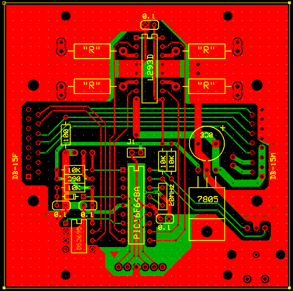
Here's a first pass at the circuit board layout. The board is 2.4" square.

The board is based on a PIC16F648A micro controller. It receives commands and data over a multi-drop bus. The connector on the left supports the data bus and power input. The right hand connector is the bus loop through. The header on the top is the in circuit programming port for flashing the PIC. The PIC connects to an L293DD which drives the air-core movement.
The board will be capable of driving more than just an air-core movement. The large yellow circle is the outline of a Switech stepping motor gauge movement. A third option is driving a standard stepping motor. There is a jumper on the board that allows choosing either 5 or 12 volts for power the driver chip.
I'm using "giant" SMD parts. Pin spacing on the ICs is .050" and the resistors are .12" by .06". There are smaller parts available, but I think I try these first.
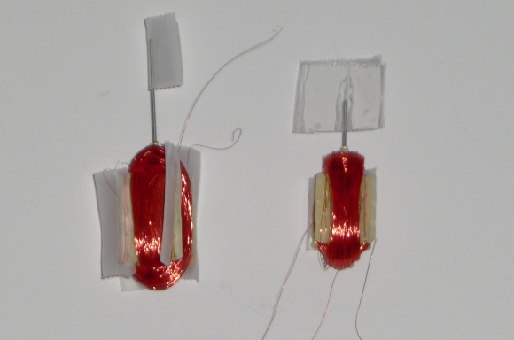
DIY Air-Core Movement Progress Update (29 July 2011)
I finally got the field windings added to my two air-core movement experiments. Both work pretty well. The larger unit appears to have more torque, but I think either would be adequate to swing a pointer.
I need to put some stronger lead wires on both. If I'm not careful I'll break the #38 wire from too much flexing. Once that's done I can test each movement when its installed in a magnetic shield.
Air-Core Movement Progress (24 July 2011)
This is one of the experimental air-core movements with the wire guides in place next to a chunk of 3/4" thin wall electrical conduit which may become the magnetic shield.
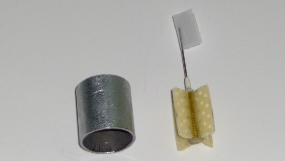
At issue is a magnetic property called remanence. This is the degree to which a material remains magnetized after an external magnetizing field has been removed. If you're making permanent magnets you wnat high remanence. If you're making shields you want low or no remanence. The remanence of the conduit is somewhere in the middle.
The problem is that the rotor magnet can magnetize the shield if the shield is too close to the rotor magnet. This will introduce error into the movement operation. Building a very compact air-core movement with hgih accuracy requires a low remanence shield.
Low remanence materials are somewhat expensive and not generally readily available to the experimenter. Conduit is cheap and easily obtained.
Possibly the 3/4" conduit will be satisfactory, or I may have to use a larger diameter.
I'll let you know.
Air-Core Pix and Mike's Tips (18 July 2011)
Here are a couple of pictures of the revised air-core movement insides. The housings are made from 0.25" brass tubing. The neodymium rotor magnets are 5 mm in diameter. The magnets are 10 mm and 5 mm in length, respectively. I got them from "The Super Magnet Man". The brass cylinders on the right are plugs that seal the housings. The rotor shafts are made from 0.033" stainless steel wire. The white stuff is Devcon "2Ton White Epoxy". It supports the rotor shaft bushing made from 1/16" brass tubing. All the brass is standard K&S Metals hobby stuff.
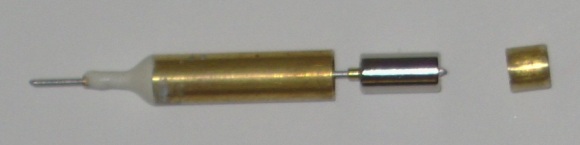
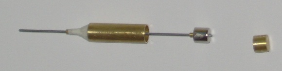
The next steps are to seal the units, attach the wire guides, and add the field windings.
Also, I have a strong draft of a new Mike's Tips article to be posted soon on the MyCockpit site. It covers how to make a very strong tee joint in thin wall electrical conduit ("EMT") using epoxy. EMT is cheap and readily available, and can be a good material for sim projects.
The idea for this article came from a question about linking rudder pedals in a general aviation simulator. A torque tube is a common solution in real aircraft, but in real aircraft they're welded. What do you do if you don't have welding gear or the money to farm it out?
One solution is to use EMT and make reinforced joints with epoxy. The tee joint pictured below is strong enough I can't pull it apart by hand. Check out my article at MyCockpit for a step-by-step description of how it went together. The article should be posted in the next few days.

Building Air-Core Movements, Again (12 July 2011)
I have a fairly good draft describing how to make a DIY air-core movement, and am building a few more movements both to verify those instructions and to try a new idea.
I'm using two magnet sizes for the rotor. The torque produced by a air-core movement is proportional to the length of the rotor, so it would seem that a longer rotor would be better than a shorter one.
However, a shorter magnet weighs less than a longer one of the same diameter and material. Since weight is a major factor in friction, less torque may be offset by reduced friction. A shorter rotor also means the movement body can be shorter.
A shorter body takes a smaller length of wire for the windings which will therefore have a smaller total resistance. A lower resistance results in higher current for the same applied voltage which translates into more torque.
There are a number of factors that interact, but in the end it's delivered performance that counts, so I'll build a few prototypes and see which works better.
Writing About DIY Air-Core Movements (30 June 2011)
About three years ago I build several versions of a DIY air-core movement based on a cylindrical neodymium magnet. They worked pretty well. In fact, they were all better than my best effort using a ceramic magnet of a few years earlier. I did a partial write up elsewhere on the site then moved on to more important stuff. (Finishing the BRFS manuscript, as I recall.)
Anyway... I decided I'd better take the time to do a more comprehensive write up of the project before I forgot too much more. So, that's what I've been up to: documenting a dusty project while I can still remember what I did.
New Mike's Tips Article (23 June 2011)
I finished a new article for my Mike's Tips series over at MyCockpit.org. It's a high level overview of Arduino. Arduino has been around for awhile, but it hasn't gotten much attention within the flight sim hobby community. No clue why. It's a family of very useful, very low cost boards. A few people have begun to work with it, and I thought some intro material on a flight sim forum would bring more attention to it.
Back to Writing (17 June 2011)
Well, at least in theory. We had guests. That was preceeded by domestic excavation as we created enough free space to host said guests. We had a very nice visit and attended a long anticipated university graduation. Life is (temporarily) quiet. Soon the graduate will return to the nest.
Prototype HUD Pictures (3 June 2011)
I meant to post these pictures earlier, but real life had other plans. Anyway, here's the inside story on the foam core board prototype HUD.
The yellow ruler is 6 inches long.
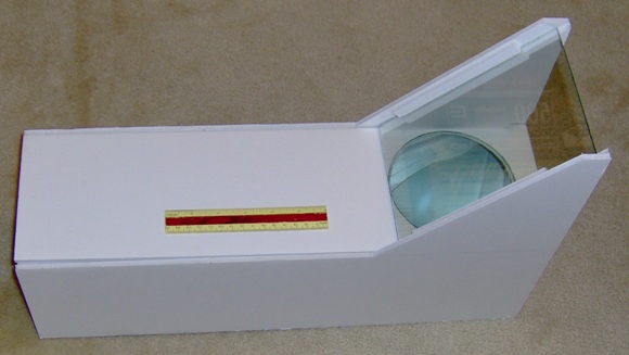

Here's what I used for an image source. It's just a piece of transparency with a grid printed on it. I backed it up with a piece of green plastic just for grins. I used a small flashlight to light it up.

Head Up Displays (22 May 2011)
Head up displays are an occasional topic in the flight sim hobby community. Flight rated HUDs are complex and expensive because of requirements for high accuracy and reliability. Most hobby conversations end with a sigh, and move on to other more approachable projects.
That may be giving up too easily. There are significant differences between simulator and flight rated HUDs that benefit the hobbyist.
A key difference is that a recreational simulator HUD can tolerate a less accurate display. A little geometric distortion may well be an acceptable trade-off for an affordable, functioning HUD. Much of the complexity of HUD optics comes from the need to correct for distortion in the image.
A second difference is that while a flight rated HUD is a collimated display that creates a virtual image at optical infinity, a simulator display is not. Its role is to create a virtual image which is conincident with the surface that displays the external scenery for the simulator. If that surface is 57 inches from the view point then that's where the virtual HUD imagery better be.
What this implies is that a simple convex lens can be used to create the HUD virtual image. You still need a partially reflective combiner, and probably a fold mirror, but those are off-the-shelf items that don't cost all that much.
I finally decided to give it a try. I picked up a 5" diameter lens through Ebay. This was an okay quality lens out of a small theater lighting fixture, not an image quality lens from an optics house. I bought small chunks of front-surface mirror and teleprompter mirror from Telepromptermirrors.com. Armed with my wife's hot glue gun and a new blade for my utility knife I prototyped a fighter style HUD out of foam core board in a couple of hours. I used a back lit transparency of a grid test pattern for the image source so I could gauge the amount of geometrical distortion.
It works.
There is a small amount of geometrical distortion that might be corrected by rear-projecting onto a slightly dome shaped screen using one of those micro projectors. However, just using a small flat LCD screen would give pretty good results.
I've updated the HUD page on my site to provide more detail.
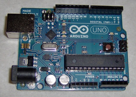
The Arduino Has Arrived (13 May 2011)
Arduino is an open source micro controller development platform based on Atmel micro controllers. Arduino is both the hardware and the software. It's cheap, widely available, and designed to give you a head start on developing your project.
The Arduino hardware exists in several different versions. The Arduino UNO, pictured below, supports both analog and digital I/O, and interfaces with the PC through a USB connection.
The Arduino software includes an integrated development environment (IDE) and a library full of useful functions. It's all C based.
The IDE is free, and there's a series of free tutorials on line to bring you up to speed.
A few people are already using Arduinos in their sim projects. I figured it was time for me to take a close look at it. For more information go to arduino.cc.
New Multimeter (9 May 2011)
It was time to pick up a new multimeter. The old one was getting a bit flaky, and besides, I wanted a new toy.
Dave Jones produces EEVblog, a somewhat off the wall video blog about all things electronic. He recently did a comparison of multimeters costing about $50. Since he not only tests them, but also takes them apart, his opinions carry some weight. He thought that the Extech EX-330 looked pretty good, so I thought I'd give it a try.
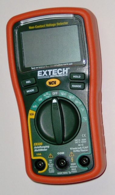
I have to admit, it's a nice little meter.
The surprising thing is that it's cheaper in-store at Fry's than anywhere I could find online.
Rebuilt Computer (29 April 2011)
I had to rebuild my production computer system after a virus/trojan/??? ate it. Win7 couldn't repair itself. When booted from the install DVD and told to repair the current installation, it found nothing wrong. When told to boot from the hard drive, it rolled over and died. I didn't lose any files, but all the programs had to be reinstalled.
Time consuming.
Grumble.
First Draft of BSDS Complete (19 April 2011)
I've finished the first draft of the head and helmet mounted displays chapter. This means I have a draft for each chapter which in turn means I have a complete first draft of the whole book. True, there's a lot missing, like projects, but it's a nice milestone.
I'm putting the finishing touches on a new Mike's Tips article for MyCockpit. This one's on airline head up displays. Should be posted in the next few days.
BSAI Still Selling (9 April 2011)
Building Simulated Aircraft Instrumentation, my first book, is still selling nicely. In fact, sales have climbed a bit over last year. I'm somewhat surprised because the majority of simulator projects seem to be airliners with glass cockpits. The book is about making steam gauge style instruments.
Maybe a second edition is in order.
Probably I should finish Book 3 first.
Optical Design Resource (6 April 2011)
Writing a book about display systems means, among other things, exploring various topics related to optical design. While there are many resources, I recently came across a particularly interesting one.
Back in 1962 US Department of Defense published Mil-Hdbk-141, "Optical Design", one of the military standardization handbooks. It's old, but 50 years doesn't change the laws of physics. What has changed are the analytical techniques and the computation tools used in optical design. This is still a technical book with lots of math, but the emphasis is on techniques that can be carried out without a computer. It's a practical book with lots of examples and broad coverage.
I don't know that I'd use it as the sole means to become an optical designer, but to gain a more than casual introduction to optical design, it's hard to beat, particualrly so because it's free. Search using "mil-hdbk-141". It's hosted on multiple sites.
Writing About HMDs (4 April 2011)
I've moved on to writing about head and helmet mounted displays. This is exciting because it's the last chapter that I do not have a workable draft of. Once I pull this one together I'll have a "workable" draft of the whole manuscript.
Once again, "workable" means coherent, if clunky, writing which has lots of content, and a non-trivial number of holes. Still, it's a nice milestone.
When I outlined this book I didn't think this chapter would have a project. Building a head mounted display with good performance is difficult and offers limited value for the time and money needed. Much better to simply buy a good quality HMD and focus the DIY efforts on areas that can't be approached through application of realistic hobby amounts of money. (Did that make sense? Translation: Buy it if you can, build it otherwise). But as I did more research for the chapter, I came to see that head tracking is an important part of HMD functionality, and tracking feels like a possible project.
Head tracking, or more properly: orientation and position tracking, allows military HMDs to respond appropriately to head movement. It's part of the real-world experience. If you're going to use an HMD to emulate that kind of experience, you need head tracking.
We've got TrackIR and FreeTrack, but I'm thinking there might be room for, and even a need for, another head tracking solution.
Writing and Drawing About HUDs (30 March 2011)
I have a workable draft of the HUD chapter. By "workable" I mean there's more content than holes (just barely). Reading it, you get a coherent story about what HUDs accomplish and how they do so, but there's still room for improvement. Explanations could be clearer, and I need to add more material. This isn't just a "how the big guys make it work", it's also "how the hobbyist can make it work".
Illustrations are wonderful for filling some of those holes, and I've been looking at different drawing tools. Most recently, I've been taking a close look at Inkscape.
I develop book manuscripts in MS Word, but I've been creating the illustrations in TurboCAD. I embed the illustrations as eps drawings, a format that preserves the crisp edges of line drawings. Word functions reasonably well with this, but eps is not a native MS file format and there have been glitches.
Inkscape is an open source vector drawing program which uses svg as its native file format; however, it can export drawings as emf files which is a native MS format. So far, no glitches.
Inkscape looks very promising. Currently, I'm the weak link. I've usedTurboCAD for years and know how to make it do what I need. Not so with Inkscape, but I think I'll give it some time.
Writing About HUDs (24 March 2011)
I'm in the process of doing research for the Head-Up Displays chapter of BSDS.
This is subtly different than actually doing the research. If I were actually researching HUDs, I'd be reading about HUDs. Because I'm in the process of researching HUDs, my focus sort of, uh, wanders.
I wandered across something really interesting: Helmet-Mounted Displays: Sensation, Perception and Cognition Issues. This is a massive survey work produced by the US Army Aeromedical Research Laboratory. It's available as a free PDF download. It's referred to as "HMD Book 2009" under the USAARL tab. If you're interested in helmet or head mounted displays this is clearly a resource you should grab.
I grabbed a copy. It'll be useful when I work on the Head-Mounted Displays chapter. Maybe my research process for that chapter will be a little more focused.
MyCockpit Article Completed and Sent (20 March 2011)
I fired off the final version of the latest Mike's Tips article. The good people over at MyCockpit should have it posted in the next few days.
More BSDS Description Revisions & Work on MyCockpit Article (15 March 2011)
Spent a little time word smithing the information page for Building Simulator Display Systems, mostly on the Collimated Display chapter.
I'm working on another article for Mike's Tips over at MyCockpit. This month I'll be covering how to measure an important performance parameter of projection screens. If you buy a screen from a professional source, you can get a gain chart. Not so, with DIY screens. Is flat white paint more cost effective than expensive screen paint? Are screen fabrics from Ebay vendors worth the cost? Measuring how screen gain changes with viewing angle can help you decide.
Revising Book 3 Description (13 March 2011)
I've been updating the description of the upcoming Building Simulator Display Systems.
Major Site Tweakage (10 March 2011)
This was a MAJOR change to the website structure. While the domain "mikesflightdeck.com" remains the same, many, if not most, of the internal file names changed. For example, it made no sense to keep the file name "upcoming_book.htm" for the page describing book2 since book2 has been available for over a year.
The main reason for these changes is that the site was originally built using FrontPage and FrontPage extensions. FrontPage is obsolete, and the extensions have been deprecated. The old FrontPage-produced HTML is not in compliance with current web standards. The new web site structure and XHTML probably aren't perfect, but they seem to pass the compliance tests, and should work better with a broader range of present day browsers.
I've also changed the navigational structure to ease browsing the site. It had been a tree structure that required a lot of up and down movement. The new structure is flatter and quicker to move through.
A downside of these changes is that bookmarks you may have into the site are likely broken. In fact, the links from search engines like Google and Bing are broken, too. I don't know how long it will take the crawlers to update their links. The vast majority of the content is still there, but the paths to it are different. In a few cases I've added transitional pages with automatic forwarding, but for most old links, you'll get a 404 type error.
In a few other cases I've modified content along with structure; the old content was either too dated or the writing style made me cringe. I intend to continue updating/revising/improving content as I have time.
Sorry for the inconvenience, and please update your bookmarks/links. Thanks.
Writing & Updating (17 January 2011)
Another edition of Mike's Tips should be posted shortly over at MyCockpit.org. This one shows how rear projection can provide a jump in image contrast compared to front projection.
This website was initially generated using Microsoft FrontPage 2000. FrontPage is obsolete, and as I'm about to upgrade my computer, I'll probably have to find something to replace FrontPage. Might be a while before I get all the pieces back together, but I'll be back.