
The Stepping Motor Approach
If you want to make an instrument that swings something with more mass, say an HSI or an artificial horizon, you'll need something with a bit more power. Stepping motors are a good choice. They are readily available and inexpensive. Stepping motors are designed to be driven by two square wave voltages that are 90 degrees out of phase with each other. The frequency of the square waves determines the speed of the stepping motor. The motor can be halted and reversed. The rotational position of the motor shaft can be tracked by counting the number of square waves sent to it. Stepping motors are excellent for precisely positioning things, like a DG compass card.

Stepping motor sources
Stepping motors are widely used in printers, scanners and disk drives. They turn up regularly in electronics stores selling surplus (check All Electronics, Alltronics, The Electronic Goldmine and Jameco), and can be easily removed from defunct equipment. Often you can find small stepping motors with conveniently sized gears already pressed onto its shaft.
 The
black stepping motor was removed from a presumably defunct, (I didn't
bother checking) very old* hard drive picked up at a swap meet for
50¢US. It was used to position the heads. The remaining three steppers
were purchased from mail order electronics suppliers for costs ranging
from 75¢US to $4US. When shopping for these motors, you definitely
should look around. I have seen literally a ten to one price range on
the same motor.
The
black stepping motor was removed from a presumably defunct, (I didn't
bother checking) very old* hard drive picked up at a swap meet for
50¢US. It was used to position the heads. The remaining three steppers
were purchased from mail order electronics suppliers for costs ranging
from 75¢US to $4US. When shopping for these motors, you definitely
should look around. I have seen literally a ten to one price range on
the same motor.
[* Not all disk drives use stepping motors for positioning heads. The motor above was pulled from quite an old unit. Drives of more contemporary design use an air-core motor that is useless for our purposes. On the other hand, if you tear down a newer drive, you will at least get a couple of extremely strong neodymium magnets.]
Another caveat has to do with the gear. When buying surplus, you never really know what the gear pitch is until you have it in your hand, so don't buy a truck load until you know for sure. Further, some don't come with a gear at all.
The stepping motors used in (very old*) disk drives often have 200 or 400 steps per revolution. Through a simple technique called half stepping, a 400 step per rev unit can be doubled to 800 steps making a single step be less than half a degree. This is small enough for this kind of stepping motor to be used to directly drive a DG compass card, making for very simple mechanical construction.
Where's Zero?
One issue with using stepping motors is that there is no unique home or zero position of the shaft. It's wherever it is when powered up. You have to provide some means for the motor controller to determine where zero or start is. Often this is done with an optical interrupter, basically a phototransistor with an LED pointed at it. A tab on the motor shaft (or other convenient part of the instrument mechanism) is positioned to block the light from the LED when the motor is moved to the start position. Just such an arrangement is used on the instrument below.
A simulated directional gyroscope
 My
green friend here, taking a break from his favorite hobby (fly fishing),
is holding a PIC controlled, RS232 interfaced, stepping motor actuated,
simulated directional gyroscope. The basis of this project is a motor
pulled from a dead disk drive purchased at a swap meet for $0.50US.
Electronic parts cost about $12US total. There might be another $6US in
mechanical stuff.
My
green friend here, taking a break from his favorite hobby (fly fishing),
is holding a PIC controlled, RS232 interfaced, stepping motor actuated,
simulated directional gyroscope. The basis of this project is a motor
pulled from a dead disk drive purchased at a swap meet for $0.50US.
Electronic parts cost about $12US total. There might be another $6US in
mechanical stuff.
 In
this side shot you can see the optical interrupter (the dark "F" shape)
and the tab on the base of the compass disk. The adjustment knob turns
a small (blue)
rotary encoder. This is a fairly low resolution encoder having only
six positions per turn (which is really 24 state transitions per turn).
This relatively low resolution would make the adjustment process too
slow, so PIC code was implemented for dual speed adjusting. When the
knob is turned slowly, one state change of the encoder moves the compass
disk one step. When the knob is turned quickly, each state change
results in 8 steps.
In
this side shot you can see the optical interrupter (the dark "F" shape)
and the tab on the base of the compass disk. The adjustment knob turns
a small (blue)
rotary encoder. This is a fairly low resolution encoder having only
six positions per turn (which is really 24 state transitions per turn).
This relatively low resolution would make the adjustment process too
slow, so PIC code was implemented for dual speed adjusting. When the
knob is turned slowly, one state change of the encoder moves the compass
disk one step. When the knob is turned quickly, each state change
results in 8 steps.
On power up, the PIC swings the compass disk around until the optical interrupter tells it where zero is. The adjustment knob shifts the internal variable tracking the compass disk rotational position. Commands received over a serial connection cause the disk to be rotated as desired.
The command format includes a five byte ID field so multiple instruments can be controlled from a single serial port. The PIC recognized two IDs. The first is a default shared by all. The second is unique to each instrument. There is a rename command that allows the second ID to be changed and loaded into the PIC's EEPROM configuration memory. This allows uniquely configuring a PIC without having to re-assemble code and flash a chip for each instrument.
Smaller motors?
As you get into instruments that are more challenging to simulate, like the artificial horizon, you will likely want to look at smaller stepping motors. The motors from disk drives are about an inch and a half square, compact, but still a bit large and heavy for some projects. This is where the smaller motors (pictured above) used for scanner and printer carriage movement come in. The inch and half round stepping motors (the two on the right of the picture) are not much smaller, but are significantly lighter. The smallest motor above is only an inch in diameter and may be your ideal choice. These motors frequently have 48 steps per revolution, which you can double by half stepping. This gives an angular step movement of 7.5 degrees, too big to use in a direct drive application. Some sort of reduction is called for and gears work well. This is fortunate as many of the motors on the surplus market come with gears pressed on the shafts. Often these are 48 pitch gears. Matching plastic (Delrin®) 48 pitch gears can be readily purchased on-line from Serv-O-Link, allowing great latitude in how you use the motor.
A simulated turbine tachometer
 Here
is an example of a project that benefits from the use of gears. It's not
because the motor must be smaller, although the motor used here is in
fact smaller. The primary benefit from using gears is the ease with
which the movement of the two pointers is coordinated. The small pointer
rotates ten times as the larger one moves from 0 to 100. An assortment
of plastic gears establish a 12.5 to 1 rotation relationship between the
two pointers and allow them to be driven by a single motor. The gearing
ratio is 12.5 to 1 rather than 10 to 1 because the large pointer moves
through only 80% of a rotation to display 100%. An added benefit of the
gearing is that it allows a stepping motor with a relatively large step
size to be used. The directional gyro project used a 400 step per
revolution motor to obtain smooth rotation of a directly driven compass
rose. This turbine tachometer works well with even a 24 step per
revolution motor due to the gear reduction.
Here
is an example of a project that benefits from the use of gears. It's not
because the motor must be smaller, although the motor used here is in
fact smaller. The primary benefit from using gears is the ease with
which the movement of the two pointers is coordinated. The small pointer
rotates ten times as the larger one moves from 0 to 100. An assortment
of plastic gears establish a 12.5 to 1 rotation relationship between the
two pointers and allow them to be driven by a single motor. The gearing
ratio is 12.5 to 1 rather than 10 to 1 because the large pointer moves
through only 80% of a rotation to display 100%. An added benefit of the
gearing is that it allows a stepping motor with a relatively large step
size to be used. The directional gyro project used a 400 step per
revolution motor to obtain smooth rotation of a directly driven compass
rose. This turbine tachometer works well with even a 24 step per
revolution motor due to the gear reduction.
A dual (concentric) pointer gauge
 A
number of interesting gauges and instruments have dual, concentric
pointer, or indicators. Take a look at the panel for the Bell 206B Jet
Ranger. Both the engine oil and transmission oil gauges are dual pointer
units, displaying pressure on the left and temperature on the right. The
rotor and turbine tach has concentric pointers as well. Some of the
navigation instruments like the ADF and HSI are also concentric
indicators. The background compass rose turns, and there is a large
pointer over laying it. Although the faceplates and indicators may be
different, the underlying mechanism for simulating them is the same.
A
number of interesting gauges and instruments have dual, concentric
pointer, or indicators. Take a look at the panel for the Bell 206B Jet
Ranger. Both the engine oil and transmission oil gauges are dual pointer
units, displaying pressure on the left and temperature on the right. The
rotor and turbine tach has concentric pointers as well. Some of the
navigation instruments like the ADF and HSI are also concentric
indicators. The background compass rose turns, and there is a large
pointer over laying it. Although the faceplates and indicators may be
different, the underlying mechanism for simulating them is the same.
This dual pointer gauge simulation has been designed to fit a 2 3/8" form factor. It makes use of two , 1" diameter stepping motors. There is enough room to accommodate 1.4" diameter motors as well. The motor pictured above is particularly nice because it came with the proper gear and only cost $1.50US. (Keep your eyes open for neat surplus like this!) The electronics is PIC based. I was initially going to use either a pair of MC3479P's or UCN5804's, one driving each motor. The $5~6US price per chip changed my mind. A single ULN2803A integrated array of darlington transistors cost only about $.50US and can drive both motors. The PIC is quite capable of handling the step sequence logic.
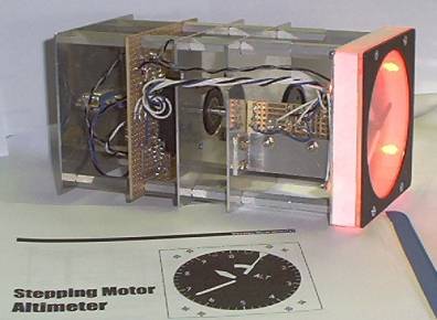
Sensitive Altimeter
 This
altimeter simulation incorporates a 400 s/r motor half-stepped for 0.45
degree resolution. There are a handful of off-the-shelf Delrin gears
that provide the 100:10:1 ratios for moving the pointers. The red glow
is from the LEDs that provide internal illumination. (It looks really
slick in the dark, but I can't figure out how to turn my cheapie
camera's flash off.
This
altimeter simulation incorporates a 400 s/r motor half-stepped for 0.45
degree resolution. There are a handful of off-the-shelf Delrin gears
that provide the 100:10:1 ratios for moving the pointers. The red glow
is from the LEDs that provide internal illumination. (It looks really
slick in the dark, but I can't figure out how to turn my cheapie
camera's flash off.
The paper under the altimeter is the first page of the altimeter project chapter in the manuscript of Building Simulated Aircraft Instrumentation. A little fine tuning on the project resulted in eight pages collecting a great many red marks. (The book is now available here.)
 The
side view below shows the basic structure used in these projects; flat
decks fastened together with standard size threaded spacers. The only
piece of bent metal is the bracket just to the left of the faceplate
that holds a small bit of perf board. The perf board holds optical
interrupters that allow the PIC to determine when the pointers are at
zero. The larger piece of perf board holds the PIC, a MAX232 for
talking with the PC and a motor driver.
The
side view below shows the basic structure used in these projects; flat
decks fastened together with standard size threaded spacers. The only
piece of bent metal is the bracket just to the left of the faceplate
that holds a small bit of perf board. The perf board holds optical
interrupters that allow the PIC to determine when the pointers are at
zero. The larger piece of perf board holds the PIC, a MAX232 for
talking with the PC and a motor driver.
Controlling and driving stepping motors
Micro controllers are a natural for driving stepping motors. The relatively high drive voltages and currents on some of these motors may cause some concern. They needn't. High drive currents are needed only to obtain the full rated torque. The torque necessary for these projects is actually quite low, so smaller, more manageable drive currents and voltages suffice. The digital outputs haven't the power to directly drive the motor, but simple transistor buffers work well. There are power driver chips that will do the job as well, but some are a bit pricey (in particular, the full bridge or "H" drivers). With general purpose switching transistors like the 2N3904/6 and 2N4401/3 available for $0.08US in quantity (Jameco Electronics), I am often willing to trade off the increased construction time with discrete transistors against the more costly integrated drivers.
Of course you may not be the penny-pinching miser I am, and may want the convenience and performance of an integrated motor driver. (Or maybe you're actually worse and simply don't have the board space for discrete components.) If either of these two conditions apply, you'll want to take a look at the Allegro MicroSystems site.
For more information on stepping motors....
If you're interested in pursuing the use of stepping motors, a "drinking from a fire hose" tutorial has been written by Douglas Jones titled, "Control of Stepping Motors - A Tutorial". A much more hands on tutorial is incorporated in The Robot Builder's Bonanza, 2nd edition by Gordon McComb. Another book addressing the topic is Irving Gottlieb's Electric Motors and Control Techniques, 2nd edition. It can also be very useful to check out the web sites of the major manufacturers as they generally have on-line catalogs with spec sheets. You'll want to take a peek at Minebea Electronics, Thomas Industries (Airpax) and Danaher Motion.