
Since Building Simulated Aircraft Instrumentation came out in 2004 both commercial and DIY hobby technology have improved. That's had some impact on the book projects.
Updated Micro Controllers
Some of the book projects call for a Microchip PIC16F828-20 micro controller. Microchip has come out with an improved micro controller, the PIC16F648A. You can still find the old one, though it make take a little effort, but it's easier and cheaper to buy the new one. There are no wiring changes and the same assembly source code will run on it. You simply have to use the appropriate linker file supplied by Microchip when you assemble the firmware. The '648A also has better support from Microchip with regard to its programming tools like the PICkit 2.
Different Electronics
Third party flight sim interface electronics has gotten better, a lot better. Actually, interface electronics in general has gotten a lot better. You can now buy a USB board that controls RC servos, or LEDs, or stepping motors, or whatever. The advantage of the flight sim electronics is that it often comes with software that already knows about Microsoft Flight Simulator, or Laminar Research X-Plane. Not having to write your own interface software is a big plus.
What this means is you can forego selecting micro controllers and building DIY instrument electronics. Just build the mechanical part then use a third party interface board to drive the gauge stepping motor or RC servo.
For examples, see the I/O Cards suite over at OpenCockpits. Or, if you want to get more deeply into electronics, take a look at the Arduino family of micro controller boards.
Improved DIY Air-Core Movement
An air-core movement is a robust mechanism for use in a single pointer gauge. There is a project in the book for making an air-core movement using a disk ceramic magnet.
Better magnets are now available. If you're interested in making an air-core movement, I suggest first reading the air-core instrument page on this site. It describes a DIY air-core movement which uses a cylindrical neodymium magnet. The construction is simpler and the performance higher.
Consider Different Digital Interface
This section covers an alternate approach to interfacing DIY instruments to your PC. It still makes use of the serial port, but is a bit more robust, less expensive and easier to build.
In The Book: RS232C
A number of the projects in the book interface through the PC’s serial port. The serial port adheres to a point-to-point connection standard called RS232C. Using RS232C, you can connect units A and B together and they will communicate just fine. Add unit C, however, and it’s a case of “two’s company, but three’s a crowd”. C’s added electrical load drags the signal down, and communication is compromised.

Even a small simulator will have several instruments. Requiring a separate serial port for each is not an attractive idea. The approach taken in the book is to build a port expander. The expander provides a number of RS232C ports that mirror the action of the PC’s serial port. Each instrument then has its own point-to-point connection. The RS232C standard is adhered to, and communication between the PC and the several instruments proceeds happily along.
If there is a downside to this approach, it is that you have to build the port expander. It’s not difficult. It’s just that you have to keep adding to it as you add instruments.
Alternatives: RS422 & RS485
One way to avoid having to continually expand the expander as you add instruments is to make use of a multi-drop standard rather than a point-to-point standard. Standards like RS422 and RS485 support 16, 32 or 64 connections per data path, depending upon the specific transceiver chips selected. These standards also tend to support higher speed connections over longer distances in noisier environments than can RS232C.
Rather than having to build a port expander, you can simply build an RS232C to RS422 or RS485 converter which is a much simpler task.
Both RS422 and RS485 use differential signaling on a pair of signal conductors. One conductor carries the signal while the other carries an inverted copy of the signal. The signal receiver looks at the difference between these two. If the difference is positive, a high level is being received. Because the difference is looked at, the signals can be heavily attenuated by long or high loss cables and still be properly received. As an added benefit, because electrical noise generally adds equally to both signal conductors, looking at the difference tends to cancel the noise.
RS422 and RS485 were developed to allow a group of devices to share a common cable system. The standards define a “standard load” that the data receiver and transmitter chip are allowed to present to the cable. It’s a small enough load that 16 “standard load” devices can be hooked to the same cable without impairing the communication. As it turned out, chip manufacturers developed “standard load”, “half load” and “quarter load” chips which means that with a bit of care, you can support 16, 32 or 64 devices per cable segment.

An important difference between the two standards is that RS485 is half-duplex while RS422 is full-duplex. Full-duplex signaling allows concurrent data transfer both into and out of the host PC, and that is the method used in many of the book projects. For that reason, RS422 will be used here.
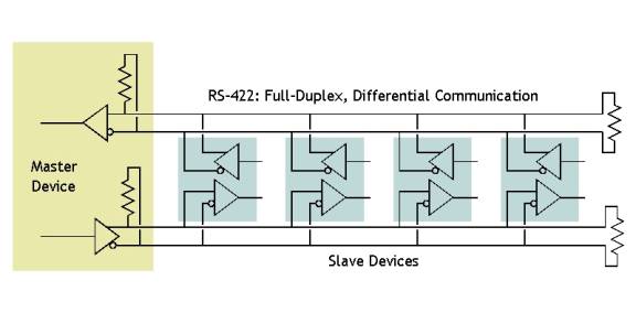
Another important difference is that while RS485 devices can communicate directly with any other device sharing the same cabling, RS422 operates with a single master device and a number of slave devices. There is no direct communication between slave devices. Slave devices communicate only with the master device. As there is no need for the simulated instruments to communicate directly with each other, and since the PC ultimately is the master, there is no problem using RS422.
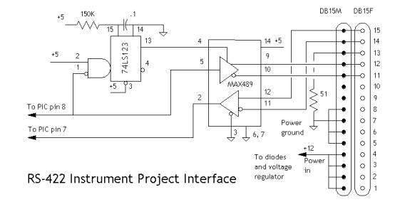
A Simple RS232C to RS422 converter
A straightforward converter can be built using a MAX232 transceiver chip connected back to back with a MAX489 chip. The MAX232 chip converts RS232C voltage levels to TTL logic levels. The MAX489 converts RS422 voltage levels to TTL logic levels. Because we’re not doing anything fancy (actually, nothing at all) with the port control signals, this basic converter deals only with the data lines, and ignores everything else.

The chips run on 5 volts, but the converter is designed to use nominal 12 volt power. A three pin regulator, a 7805, is included to insure clean power. A few protection diodes have been thrown in to protect against inadvertent power polarity problems.
Instrument Mods
Of course, if you’re going to use RS422, it needs to be RS422 on both ends. The instrument designs in the book make use of RS232C, so a few tweaks are in order. We could simply use an RS232C to RS422 converter for each instrument, but that’s pretty clunky. It’s better by far to make some simple changes in the instrument electronics.
Step one is to replace the MAX232 with a MAX489. Unfortunately, these chips have differing pin outs, so you can’t simply unplug one and drop the other in. So, if you’ve already built the electronics, a bit of rework is called for.
The next step is the addition of a second chip, a 74LS123. Because RS422 is a multi-drop standard, a number of devices can be connected to the same data wires. However, only one device can place data on those wires at any given time. The MAX489 has an enable pin that is used to activate the data transmitter and place data on the wires. The 74LS123 will generate a pulse to temporarily enable the MAX489 when data is to be sent.
You may be wondering why we don’t simply let the PIC micro controller enable the MAX489. Well, we could, but it makes the communication path vulnerable to a crashed micro controller. If one of the PICs somehow gets hung, it might very well leave the transmitter enabled which would prevent any other device from sending data. Adding the 74LS123 doesn’t eliminate that possibility, but it makes it much less likely.
The final step is mechanical. The rear plate on the instrument should have holes for two connectors. One connector supports data in and power while the second connector supports data out. This allows you to daisy chain the data connections from one instrument to the next.
Note that power is not daisy chained. Daisy chaining high current conductors, like power, is something to be done with care and forethought. In this case, the use of small data connectors (the DB-15’s), and the potentially large number of connections end-to-end, means that daisy chaining power is not a good idea. So, while data can be daisy chained, power is best connected directly from each instrument to a power supply. Here's the wiring for the cable for use between the RS232 to RS422 converter and between the instruments.
