
PC Board Options (23 December 2008)
Completed a good, solid draft of this appendix.
Everything in the book has been drafted. The page count sits at 594. Missing illustrations account for three. The table of contents and index are budgeted for six and five, respectively. That will bring the total page count to 608.
I'm now editing for clarity, working on the missing illustrations, and verifying projects.
Joysticks Chapter (21 December 2008)
I expanded the coverage of control loading. There is now more background material on springs, hydraulic dampers, and gas springs.
Engine Controls Chapter (18 December 2008)
I've got a good draft of the Engine Controls chapter. It's missing one illustration, but otherwise complete.
The chapter project uses slide potentiometers for position sensors. I've chosen Bourns PTE series pots. This is a "long-life" series with a rated lifetime of 100,000 full range movements. Standard life slide pots often have a rating of only 15,000 full range movements. A standard slide pot costs on the order of $2~3. The PTE series runs just under $7. Not too bad; for three time the cost you get six times the life.
Engine Controls Chapter (13 December 2008)
I'm continuing to work on the project write-up for the engine controls chapter. The project is a basic mechanism for a lever-style engine control. Here's the overview illustration:
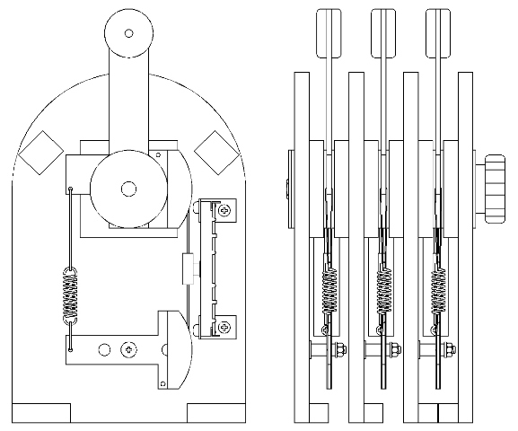
The intent is to demonstrate solid, low-cost techniques that result in excellent performance.
This is the last project write-up needed to finish the draft manuscript. I'm very close to having a complete draft of the book, but a great deal of work remains. I'll be doing more prototyping. I "improved" some of the projects during the writing. These must be built again from the book descriptions to assure that the changes actually are improvements. Then there's editing for clarity, checking for holes in the overall scheme of the book, indexing, creating the cover artwork and copy, and so on.
Pedals and Throttles (9 December 2008)
I added a small section to the Pedals chapter. I hadn't realized it was missing. After uncountable read-throughs, I finally noticed. It's the section that addresses which characteristics to mimic when building a simulation of something. Of course, there is no one answer. It's both subjective and dependant on what resources can be drawn upon. The goal of the section is to suggest a methodology so you get the most bang per buck given your personal desires, resources and target aircraft. Anyway, that's done.
Currently, I'm attempting to finalize the project in the Engine Controls chapter. It's a modular lever throttle based on hardware store items (mostly). It uses a linear pot for the position sensor which it treats very gently to maximize its life. It uses a spring to take up any mechanical play in the linkage, and it has a friction adjustment for lever motion. Because it's modular, you can put as many units side-by-side as needed to build whatever throttle quad you want.
Panels Chapter Updates (4 December 2008)
I revised and completed the chapter on Panels. It was enough of a change that I'm sure a read through in a few weeks will result in some hopefully minor changes. But as it stands now, it's not looking too shabby. Not at all.
Scenery Display Chapter Updates (26 November 2008)
I revised the Scenery Display chapter. Half the revision work was just transcribing the red markups from the paper manuscript to the electronic document. The reminder was a re-write of the section about using a Fresnel lens in front of a monitor. When you don't have the room (or money) for a projection system, a Fresnel lens can add to the flight illusion. You get a little magnification, and the image is moved a bit away from the viewpoint.
I didn't feel that my earlier version clearly described how the lens worked optically, or what the tradeoffs were. Three new drawings and a lot of revised text have improved the situation.
This added two pages to the manuscript page count. It's now at 95% target size.
I/O Bus Adapter PC Board (21 November 2008)
The circuit board for one of the I/O Options chapter projects arrived yesterday. Digging for parts and assembling it took about an hour. This is a revision of the original I/O bus adapter project. The I/O bus is basically a full duplex RS-485 shared connection that allows multiple devices to share a single serial com port.
The RS-485 standard limits the number of standard bus loads to 32 per bus segment. A bus load is an indication of the amount of signal power a data receiver pulls from the bus in order to reliably receive the data. Put too many hunger receivers on the same bus segment and none of them function properly.
The original bus adapter project supports 32 devices on a single bus segment. A device might be a simulated instrument like a VSI, a 16-switch interface module, or an LCD radio head. (These are all projects in the book. ) Thirty-two is a good number of devices for a small plane sim, but step up to a twin and 32 starts to look a little on the small side. It's easy enough to expand on this, so I thought, "Why not do it now?"
This revised version has two bus segments and will support 64 devices. It's easy to expand beyond this, but I had a board-size versus performance tradeoff to make. ExpressPCB has special pricing for boards which are exactly 2.5" by 3.8". I wanted to keep the price under control while still providing support for a large number of devices. I think getting an adapter which supports 64 devices for the special pricing is a "sweet spot".

Simulator Enclosures, Interfacing with MSFS & Sound Chapters (19 November 2008)
I just zipped through the chapters on simulator enclosures, interfacing w/MSFS, and sound, typing all the handwritten editing notes. I now have clean copy to add more handwritten notes.
I got email from ExpressPCB. They have shipped the serial com port to RS-485 boards. Delivery is scheduled for tomorrow
I/O Options Chapter (15 November 2008)
I've completed this pass through the chapter. I'll do a final artwork review of the revised adapter project, and order a PC board to verify the revisions.
I/O Options Chapter (12 November 2008)
I finished the intended chapter updates then noticed the descriptions of the chapter projects were rather lame, and also decided to update one of the projects. I'm using a duplex, serial RS-485 bus to connect all the projects to the simulation computer. The project is a serial com port adapter for this bus . (It could theoretically talk USB as well, but USB is a bit more complex.) I decided to expand the adapter to include two RS-485 connections. The change adds all of one chip and one connector. Plus, the whole thing fits on a cheap specially priced prototype PC board from ExpressPCB.
So... I need to keep working on the chapter, double check the artwork for the revised project, order the PC boards, build and test the project. Then, maybe, just maybe, I'll be done with the chapter.
I/O Options Chapter (5 November 2008)
I'm well along in restructuring and renaming the Hardware I/O Options chapter. I've added a large section that presents an example I/O structure for a single engine sim. It's a much stronger chapter that better explains the key concepts.
Hardware I/O Options Chapter (2 November 2008)
Re-reading the Hardware I/O Options chapter didn't leave me feeling any warm fuzzies. So I'm revising it; adding more examples and illustrations.
Input Arbitration Module Tested (27 October 2008)
The arbitration module and the switch input module work well together. There were a few firmware errors in assigning pin numbers which were quickly resolved. The firmware listing in the manuscript was revised accordingly.
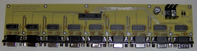
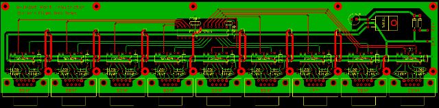
Input Arbitration Module PC Board (23 October 2008)
The circuit boards for the input arbitration module were delivered yesterday. These were made by ExpressPCB as were the 16-switch input modules. Nicely done, shipped on schedule, no complaints.
Here's a picture of the assembled module.
Tweaking the Switch Input Chapter (20 October 2008)
I revised the artwork for the DIY, single-sided version of the 16-switch input module, one of the chapter projects. The artwork is now very similar to the the layout used to make the double-sided board at ExpressPCB.
Input Arbitration Module (18 October 2008)
As a home simulator project grows, the number of switch inputs grows with it. The switch input module provides the means to add switches in a modular fashion. Need more switches? Add another module. The modules share an input port. Simply daisy-chain the cable through another module.
When there are only a few modules, software can poll the modules for changes in switch positions. As the number of modules grows, the delay between a switch being flipped and the simulation reacting to it starts to become objectionable. One solution is to enable a module to automatically send a message upon switch changes rather than wait to be polled. This is fine as long as only one module sends at a time. If messages overlap, both are corrupted.
There are a number of approaches to resolving this sort of situation. The approach I've taken is similar to that used in the early days on mini-computers. It's not the most elegant, but it's robust and easy to implement with inexpensive parts. It's an arbitration module that coordinates use of the input channel to the simulation computer.
A switch input module, or any module that sends data to the simulation computer, asserts a request line to the arbitration module and waits until it receives a grant. The arbitration module will only issue one grant at a time, and will hold the grant asserted until the request is dropped. An arbitration module arbitrates among eight input modules.
The arbitration module itself has a request output so that multiple arbitration modules can be linked together for simulators having more than eight input modules.
As I was pleased with the quality of the switch input module printed circuit board made by ExpressPCB, I've ordered arbitration PCBs from them as well. They should show up next week.
Switch Input Printed Circuit Board (10 October 2008)
The circuit boards for the 16 switch input module, ordered from ExpressPCB, arrived on schedule today. I'm very pleased with them.
The new board is the lower of the two in the picture. I included the original prototype for comparison (the upper board). It was made DIY style using the toner transfer method.

Both the circuit and the layout have evolved. I simplified the circuit slightly and eliminated one chip. The layout is tighter. The switch inputs are now grouped together so that a flat cable can optionally be used. The voltage regulator is bolted to the heat sink and board to reduce flexing of the regulator leads.
I had four identical circuit boards made at a total cost of $105. Not counting my time, I could have made single-sided versions for less. But this is something of an apple to oranges comparison. The professionally made boards are double-sided, have no jumpers, and have plated through-holes. Also, I have far too much electronic junk in my garage, so my cost of materials approaches zero. When you start adding the costs of your time, materials, special tools, and mistakes, the professional boards hold their own. A big chunk of the cost is a $55 set up fee and the cost of shipping. Get a few friends together for a group order and the per board cost drops quickly.
Switch Input Printed Circuit Board (7 October 2008)
I prototyped the original switch input module back in March 2007. I developed basic artwork for a single-sided printed circuit board, added it to the Switch Inputs chapter and moved on to other things. I'm now revisiting the project and investigating professional approaches to having the PC boards made. I redesigned the board artwork and ordered a few boards from ExpressPCB. The process is perhaps not the cheapest, but the PC layout software is easy to use, and ordering is a snap. I should have the new boards by the end of the week. I'll let you know how it works out.
Project Printed Circuit Boards (30 September 2008)
The book presents several projects that involve electronics. Each project is documented with a complete schematic and circuit board artwork. The board designs allow for single-side construction. Most of the traces are on one side. The few remaining conductors can be added as jumpers. So, if you wanted to make the boards at home using the toner transfer method, you certainly could. In fact, the projects were prototyped using that very approach.
There is also nothing to prevent you from have boards made professionally. There are a number of PC board houses that will make small quantities for a reasonable price. Given the convenience, I suspect this approach will be the preferred one. So, I'm giving it a try myself.
This is a screen grab of the free board layout software from ExpressPCB. The project is the 16 switch input module from the Switch Inputs chapter.

Switch Inputs Chapter Edited (27 September 2008)
I've finished the edits to the Switch Inputs Chapter. It now has a few more illustrations and two more pages. The result is that the firmware is better explained. I need to read through the whole chapter to make sure it hangs together well, but just the thought of looking at makes me cross-eyed. Time to put it aside for a while.
Warning & Status Lights, and Switch Inputs Chapters (24 September 2008)
Wrapped up the edits to the Warning & Status Lights chapter, at least as much as these things are ever finished. I've completed the changes I had intended to make, but I fully expect that I'll find something else when I review it several weeks from now.
The Switch Inputs chapter is next. The firmware overview needs some help.
The manuscript page count is at 560. The book's missing a project, an appendix or two, a few dozen illustrations, a table of contents and an index. Looks like it'll come in close to the projected 608 pages. I have a lot of project building to do. Designs get "improved" during the writing. Building verifies that these evolutionary steps really are better.
Warning & Status Lights Chapter (20 September 2008)
The Warning & Status Lights chapter is one of the oldest. It may even be the first I wrote. It's been extensively revised, but during a recent re-read it was apparent there's room for still more revision. I've added a firmware flowchart, made some tweaks to the firmware, and am expanding the description of firmware functionality.
DIY Instruments Chapter (16 September 2008)
I'm filling in holes.
I wrote the DIY Instruments chapter and built the chapter projects quite some time ago. As subsequent chapters came into being, my descriptive approach evolved. In particular, I found that flowcharts help explain firmware. I may be over explaining things, but I don't think so. Firmware is confusing because of its size. The little micro controllers have a limited repertoire of instructions. You can only cram so much processor on a tiny bit of silicon, but what you get is cheap and fast. On the down side, you end up with a lot of code, and that can be a bit off-putting.
The code listings have a lot of comments. Even so, I think starting with an overview supported by a flowchart is a good thing.
So, I'm now going through early chapters and updating the firmware descriptions.
Motion & Force Cueing Chapter (12 September 2008)
I have a strong draft completed, (and already see where I can improve it).
I now have at least some version of every chapter. There are a number of holes, some major.
It's beginning to look like a book.
Motion & Force Cueing Chapter (9 September 2008)
I'm about two thirds through creating a decent draft of the chapter on Motion & Force Cueing. I had pages of notes from longer ago than I care to admit. Since making those notes, many of the motion system companies have vanished, either being bought or just leaving the business. Another important change is a small but important growth in DIY motion systems. As I've pulled the draft together I've made sure to reflect the changes in both areas.
This is an advanced topic, right on the edge for an introductory book with broad coverage. It will be a short chapter, but full of information.
Position Sensors Chapter Revisions (3 September 2008)
I keep a hard copy of the manuscript in a three-ring binder, and make notes on it as I have flashes of brilliance.
Well, not really. What really happens is I make notes when I read through the manuscript and have flashes of despair, thinking "Did I actually write that?"
Periodically, I have to go through the manuscript along with its collection of red scrawling notes and bring it up to date, which I just did with the chapter, "Position Sensors". I also added new material to further cover the topic a Hall Effect sensors. Here's an illustration from that new section.
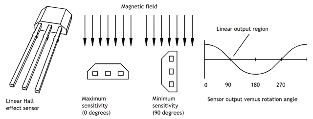
Originally, I just covered the Hall Effect theory and pointed to commercial products for those interested in position sensing with Hall devices. This is a bit expensive. The new material explains how to use the $1~2 Hall Effect field sensor along with a simple magnet structure to make a nicely linear rotary position sensor.
Hardware I/O Options Chapter (1 September 2008)
I've got a solid draft. I'm sure it'll be covered with red marks before too much longer, but it's much closer to finished than it had been a week ago.
I've now bumped the draft page count up to 90%. I am officially "90% done". That means I can start working on the second 90%.
Beating on the Hardware I/O Options Chapter (27 August 2008)
After reading through the Hardware I/O Options chapter draft, I decided it dipped too deeply into techie details about I/O possibilities. It really needs to discuss the specific I/O requirements of a simulator. So, I'm hacking on the draft, removing extraneous detail and adding requirements discussion. This looks to tie in much better with projects in other chapters. It leads to a better understanding of why certain I/O choices were made and how they all work together.
Computer Drawn Instruments Chapter (26 August 2008)
I finished a revision of the chapter on Computer Drawn Instruments so that it now reflects FSX rather than FS9. Probably need to add a few illustrations.
Computer Drawn Instruments Chapter (24 August 2008)
I've been working through some of the Panels & Gauges documentation for FSX. I've succeeded in producing a demo panel on a second screen. All the gauges are stock MS gauges. Note that the background is black and the gauges are round. I consider the roundness quite an achievement. FSX tries hard to make full use of all screen real estate. It scales things to fit. It's a nice feature until you don't want it and don't understand how it's working its magic. I can't claim to understand all of it, but I think I've got a grasp of this little bit.

The knowledge behind this will be condensed into a few paragraphs in the Computer Drawn Instruments chapter. This is how to produce a custom panel layout that will allow you to place the instrument monitor behind a nice looking instrument panel facade. The scenery can be displayed out in front on an impressively large monitor or projection screen.
FSX Panel and Gauge Tutorials (22 August 2008)
The brown square and its contents are the result of the working with the building XML gauges tutorial in the FSX SDK. The SDK also includes an XML editing tool ("ACE Tool") which is helpful but temperamental. Sometimes the preview function works, and sometimes it doesn't. At least it seems to produce cleanly formatted XML.
In any case, the left portion of the image is a 1440X900 chunk of scenery while the right portion with the black background is the tutorial test gauge set. It's straightforward to build a panel of floating gauges that you could display on a monitor positioned behind an instrument panel facade.

Computer Drawn Instruments Chapter (21 August 2008)
Been working through some of the tutorials on building gauges and panels to refresh my memory and make sure I keep the FS9 -> FSX differences in mind. This chapter isn't big enough to cover the details of panel and gauge building, but it can show the direction to what's possible.
And there's actually quite a lot you can do without much difficulty. Just moving the instrument panel to a separate monitor can boost the sense of immersion. If the instruments are on one display, the outside view can be moved farther away, perhaps even projected if the budget's there. With the instruments and the scenery at different eye focal points, there's a subtle subconscious cue that distinguishes between inside the airplane and the outside world of the scenery. The flight illusion gets a bit better.
Computer Drawn Instruments Chapter , MS ESP (20 August 2008)
I wrote this chapter quite a while ago. In fact, it was before FSX came out, and things have changed. So, in addition to the normal editing cleanup, I've got some updating to do as well.
ESP is the commercial simulation offering from Microsoft. FSX is built on the ESP technology. Because ESP is a commercial product, there is now extensive online support in the form of the MSDN ESP Developer Center. This is a good thing. All the documentation that was in the SDK that shipped with FSX Deluxe is online, plus they've added videos, blogs and a forum. If you're interested in the highly technical details, this is a great resource.
Sound Chapter (18 August 2008)
Completely rewrote the chapter on sound in your simulator. Decided there is no great value in a chapter project. DIY doesn't save any money here.
Removed some of the appendix material, good stuff, but a little off the mark for the book target.
Stepping Motor Instrument Movements (16 August 2008)
While air-core movements swing the pointers in a great many automotive and marine gauges, they don't swing them all. Stepping motors are used in some.
The stepping-motor movements contain a very simple 2-phase stepping motor followed by a 1::180 reduction gear train. Even though the stepping motor has a large step size, the gearing results in a 1/3 degree step size on the output shaft. These aren't real power houses, but they do have adequate torque to swing a pointer at up to 600 degrees per second. They're compact enough to fit into a standard 2" diameter A/C instrument shell, and the current required to drive them is a maximum of 20 milliamps, something within reach of a micro controller. (Download specs in PDF format here.)
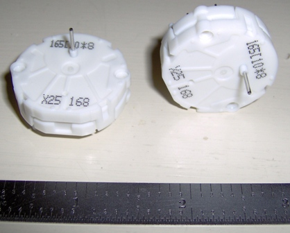
This particular model (the only model available through the vendors on Ebay) has an internal stop and is limited to 315 degrees.
The internal stop removes the need to use some sort of indexing sensor to determine where the needle is positioned on power up. You simply write the initialization firmware to rotate the needle 315 degrees counter-clockwise. The needle turns until the internal stop stalls the motor. From then on it's just a matter of keeping track of how many (up - down) steps the micro controller has sent the movement.
The 315 degree limit somewhat restricts what you can do with this. No compasses, DGs, or sensitive altimeters, but airspeed, EGT, flap position, oil pressure, fuel quantity, and so on look to be slam dunks.
These movements are made by Micro Components SA, a member of the Swatch Group. They have been on my radar screen for awhile, though at a low priority. Recently I noticed that they were available retail from two different vendors on Ebay, so I had to buy a couple. They showed up today giving me something else to toy with instead of writing.
Actually, I have managed to get some writing done. I made an editing pass through the Interfacing with MSFSX chapter, correcting a number of smaller issues while noting that I have more there to do. The section on setting up a programming development environment was originally written with Microsoft Visual Studio 2005 in mind. VS2005 did not incorporate the Win32 platform SDK by default. I had to add instructions on how to do so. Well, it looks like VS2008 does default to having the platform SDK. So, I've got to update that part.
Chapter 4: Engine Controls (13 August 2008)
Back to engine controls.
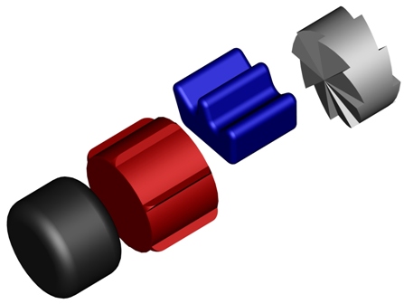
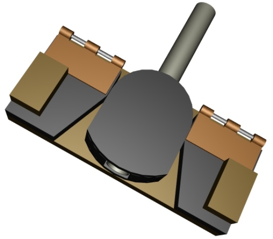
In the early days of human factors in aviation, aviation controls were given standardized characteristics. Throttle knobs are rounded and black, mixture knobs are red and have raised ridges, and prop controls have recessed grooves and are blue. The fourth knob with radial ridges is a supercharger control.
Then along came HOTAS...
Chapter 17: Simulator Enclosures (12 August 2008)
An enclosure is another simulator element that adds to the flight illusion. It deepens the feeling of immersion by actively contributing components that say "airplane!", by isolating you from distracting sights and sounds of the real world, and by tying all the disparate controls, annunciators, instruments, and scenery displays into a connected whole.
I've just completed a draft of this chapter.
Chapter 4: Engine Controls (10 August 2008)
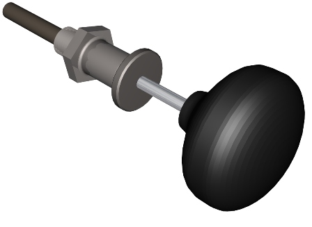
Random vernier push-pull engine mixture control.

Chapter 4: Engine Controls (9 August 2008)
Random push-pull throttle with friction lock.
Hey, gotta cover the basic stuff too!
Chapter 4: Engine Controls (8 August 2008)
So here I am, working on the Engine Controls chapter. (Yes, I know. I do tend to hop around.) I drafted this chapter some time ago. I had placeholder pictures for the illustrations, so I'm now producing the line drawings that will go in the book. This particular group of illustrations go in the section that overviews the range of engine controls in real aircraft.
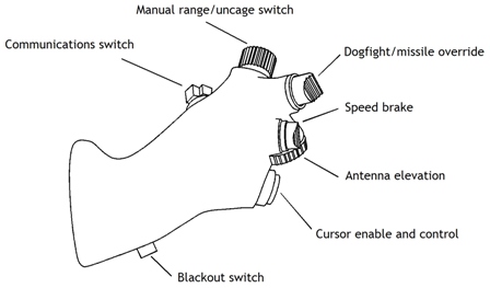
The main thread in the book is how to create a flight sim experience, ranging from okay to awesome. If your preferences lean toward the awesome end of the scale, you quite likely need to implement the same controls in your sim as a pilot uses in a real plane. And if you're exploring simulator options, it can be really helpful to have an idea of what's important and how complex different amounts of awesome might be.
That's the goal of this section, at least with regard to engine controls. There will be illustrations of simple push-pull GA throttles, of multi-engine throttle quads, of helicopter collectives, and of the F-16 HOTAS throttle grip pictured below. The goal is to communicate an idea of what's important in producing a quality flight sim experience, and what your options might be in pursuing it.
Chapter 0: Recreational Flight Simulators (2 August 2008)
Okay. I have officially (or maybe officiously, I'll see on re-reading) completed the first draft of the introductory chapter, "Recreational Flight Simulators". This brings the total of currently drafted material to 533 pages.
I'm probably going to cut some material. I'm in danger of running over. I figure 608 pages is a reasonable total. That's an even 19 signatures of 32 pages each. I hadn't planned on quite as much intro material, but I'm liking it now. So something's got to go. I've got some appendix material that's a bit too much detail for the book... hmmm, a page here, a page there...
Chapter 0: Recreational Flight Simulators (27 July 2008)
This is the introductory chapter. I had originally intended to put this material in the Introduction. No one reads book introductions though. So I figured I'd try writing it as a separate chapter and see if there's enough material to justify itself. I've bounced back and forth on this. Intro-chapter-intro-chapter-sigh. I'm leaning toward chapter at this point.
The book is supposed to be an advanced introduction to the home-built sim hobby. So, in theory, a lot of people at ground zero (experience-wise) will buy it. (What I'm hoping is that these people will post to forums asking all kinds of newbie questions, and all the answers will be 'Welcome to the mad house, now go buy Mike Powell's book'.) That kind of means I can't just dive into the details. I need to be up front with these new guys and explain that once you start, there's no way out, kind of like trying to eat just one potato chip. Sticking something really important like this in an Introduction that nobody reads just doesn't seem right. The material just has to have its own chapter.
So, anyway, that's what I'm doing, and I'm about halfway through the first draft.
Editing the Joystick Chapter (27 June 2008)
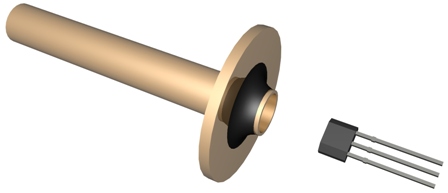
I've created a number of new illustrations for the Joystick chapter to cover the change from potentiometers as position sensors to Hall sensors. There are at least two or three more drawing to do, and a great deal of re-writing. Then I get to build the project to check for errors.
Here's a picture that won't be in the book, though something similar will be. This is the way the hall sensor will be supported: stuffed into a brass tube and held by RTV.
Control Yoke Chapter Progress and Hall Sensors (20 June 2008)
The Control Yokes chapter is now a 32 page draft. It's far enough that I've printed out a hardcopy for further editing. I think more explanation about real control yoke linkages would help, but overall the chapter is coming together nicely. As time permits I'll build the chapter project following the chapter directions as a check on completeness.
I'll be heavily revising the Joysticks chapter to use Hall sensors in place of potentiometers. Pots get good coverage in the Control Yokes and Pedals chapters. The joystick project is a floor-mounted stick with small angular motion. This makes it a good candidate for using a linear output Hall sensor.
By "Hall sensor" I'm referring to the $1.30 Allegro A1301 magnetic field sensor rather than the $35~50 Honeywell/Clairostat rotary Hall position sensor.
If you rotate a Hall sensor in a uniform magnetic field, the sensor output varies as the cosine of the angle of rotation. The cosine (or sine, if you prefer) is not particularly linear. In fact it's pretty darn wavy. However, If you zoom in on a small portion of the cosine (or sine) curve, that changes. If you look at the regions around cosine(90 degrees), sine(0 degrees), cosine(270 degrees), and sine(180 degrees), the curve flattens out. For about 45 degrees the curve is flat within about 2%, and that is pretty darn good.
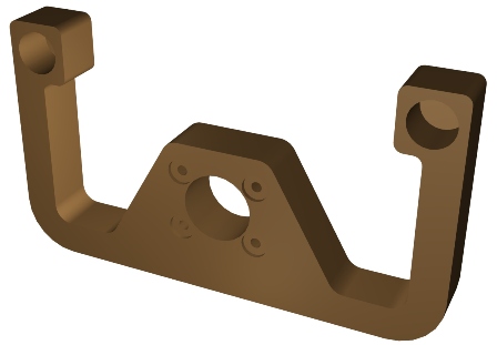
To use this approach you need a uniform field strong enough to produce full output from the sensor at 70 degrees and 110 degrees. The field should be uniform over a large enough volume that minor lateral movements of the sensor don't produce noticeable errors. Finally, the magnet structure shouldn't generate stray fields that influence other, nearby sensors.
This picture shows a rudimentary magnet structure that meets those goals. The magnets are 3/4" diameter ceramic disks. (I could have used neodymium, but would have had to order them. Ceramic magnets are available locally.) They are large enough to provide a comfortable volume of uniform flux in the gap between the two. The steel brackets and stack of steel washers provide the magnetic back circuit so there is little flux outside the gap. Finally, by changing the number of washers, the gap size can be varied and this adjusts the magnetic field strength in the gap.

Bottom line: This works, and it's cheap.
I'll be using this approach (with a more robust magnet structure) for the revisions of the joystick project.
Plodding Continues (10 June 2008)
Text for the Control Yoke chapter project has been drafted. I'm back working on the drawings.
Hall Sensors (2 June 2008)
It occurred to me that I have used potentiometers as position sensors in too many book 2 projects. It's not that potentiometers are bad sensors, in fact, some models are very, very good. It's that book 2 is supposed to demonstrate, through their use in projects, various techniques and items for use in DIY sims. Showcasing rotary pots in every project shortchanges the reader. What about other approaches, like Hall-effect sensors?
One could argue that the Honeywell HRS100 Hall-effect rotary position sensor is mechanically a drop-in replacement for a rotary pot, so why bother? One could, except that there are less expensive approaches than the HRS100. The best price I've seen lately is on the order of $35 each. For about $1.30 you can buy a linear output Hall-effect sensor, the Allegro A1301. It's not a position sensor, it's a magnetic field sensor. When you buy the HRS100, you're getting the magnetic field sensor imbedded in a magnetic circuit that linearly varies the strength of a magnetic field applied to the sensor as you turn the shaft. There's no secret regarding how to do that, but it does usually entail the use of special materials to avoid inaccuracies due to magnetic hysteresis . So you really do get something for your money when you buy an HRS100.
But what if you don't need a full 90 degrees of rotation sensing? What if you have something like toe brakes or a floor mounted joystick that only moves 40 or 50 degrees? Then the design parameters change.
Some simple bench tests show that an Allegro A1301 Hall-effect sensor, a pair of cheap ceramic hobby/craft magnets, and a few bits of steel can produce a rotary position sensor with better than 2% linearity over a 40 degree measurement range.
So... It looks like the best place to showcase rotary potentiometers is the control yoke chapter. The joystick chapter, with its floor mounted joystick project, seems a natural for showcasing DIY rotary Hall-effect position sensors. Sadly, the joystick chapter had been "complete".
Plodding along (29 May 2008)
I've made one pass through the Control Yoke chapter roughing out the illustrations. I'm now expanding the text. This, of course, has resulted in reordering a few of the sections which means the detail in the illustrations must change. So, once this wordsmithing pass is complete, it's on to pass two on the artwork. Usually this process converges. At some point I decide the chapter draft is pretty much there and move on to building the project as described in the chapter. This is the "proof in the pudding" step which leads to more revision. I did say this converges, didn't I?
HUD Book Overviewed, Looking at Yoke Options (23 May 2008)
I added an overview of Head-Up Displays, Designing the Way Ahead to the HUD page.
I've also been exploring different approaches to making control wheels. I'm not trying to build a perfect replica of any given yoke, rather the goal is to demonstrate technique. I want to communicate skills for using commonly available materials to create flight controls of arbitrary shape, how to mount a yoke to a control shaft, how to embed wiring, and so on.
As usual, what I thought had been nailed down a long time ago continued to evolve while I had my back turned. I need projects that stay pinned down long enough for me to write them down and move on to others. Unfortunately, when I start working on the drawings new ideas keep popping up.
HUD Book (18 May 2008)
I finally managed to borrow a copy of Head-Up Displays, Designing the Way Ahead by Richard L. Newman. This is an extensive survey work covering aviation HUDs. It focuses on design criteria rather than technology. There is a great deal of what a HUD should accomplish, but very little of how to do so. Nonetheless, it's interesting, and I'll be writing more about it on the "Head Up Displays" page over the next several days.
Book 2 Milestone (16 May 2008)
Okay, maybe it's just an inch-pebble, but it's still progress. The manuscript for Building Recreational Flight Simulators hit 500 pages today. I'm estimating 608 pages total which includes table of contents, index, and so on.
Why 608? It's an even 19 signatures. A signature is a group of pages which are printed together. The printer I will probably use puts 32 pages in a signature. The sheet fed press prints a four by four array of pages on each side of a large sheet of paper. After folding and trimming it results in 32 pages in the book.
In any case, I'm busily churning out illustrations that show how the Control Yokes chapter project goes together. Tossing in a few words, too, but mostly it's drawing time.
Tiny Stepping Motors part 4 (15 May 2008)
Just thinking out loud. If variable reluctance won't cooperate, perhaps permanent magnets will.

Control Yoke Chapter Project Drawings (13 May 2008)
The construction drawings for the Control Yokes chapter project are starting to come together. The project is a general aviation style yoke based on drawer slides and industrial mounted bearings. I tried to stick to materials available from home building stores, but there was just no substitute for the industrial bearings that came close in performance. The yoke has springs for control loading. High end potentiometers play their parts as position sensors. These are the same Bourns model 6639S potentiometers I have written about before. The mechanical design minimizes backlash for smooth, precise handling.
This is in general what it looks like, though I'm still tweaking.

Tiny Stepping Motors part 3 (11 May 2008)
It works. Grudgingly, but it does work. Unfortunately, it doesn't work well enough. The biggest issue is that it's right at the limit of my fabrication ability. I'm using telescoping brass tubing for the bearings, and I've got too much play. This sets a minimum possible gap between the rotor and the stator poles. The motor produces more torque with a smaller gap, but if the gaps is too small the bearing wobble lets the rotor hit the stator. There are a few other issues, but this is the most troublesome.

I chose the telescoping tubing approach because the hollow center can be used as a wiring channel.
Well, there are other approaches for the future. For the time being I'll table this and move on to more pressing issues. I have a few more things to do on the updated air-core movements, and there is a growing box of parts for the Yokes chapter project.
Tiny Stepping Motors part 2 (10 May 2008)
I'm simply not getting the performance from my first version stator. I'm going to the more standard three phase stator. It's easier to build. Because the poles are farther apart it should relax the dimensional demands on the stator to rotor gap.

Update: New version stator is much better.
DIY Instrument Tutorials and Tiny Stepping Motors (6 May 2008)
I spent several days writing three introductory tutorials about do-it-yourself instruments. They are posted in the tutorial section of the MyCockpit forums. There is one each for air-core movements, stepping motors, and RC servos. You can read them here, here, and here.
By the way, If you're not familiar with MyCockpit, it's an excellent English language forum dedicated to flight sim cockpit building. Check it out.
As I was developing the tutorials, I was reminded of the challenges of simulating instruments incorporating drum style displays. Some altimeters have a drum display for setting barometric pressure. Some military altimeters use a drum display to indicate hundreds and thousands of feet. Then there are fuel flow indicators, chaff counters, and so on.

Drum displays are essentially the same as mechanical odometers found in older cars. Each digit has a wheel with 0 to 9 printed on the outer edge. Each wheel has gear teeth that allow it to be turned. It's actually a clever mechanical counter that is remarkably simple for what it does. They just never seem to be available in the correct size for simulating instruments, and then there's the whole issue of interfacing their little mechanical selves to the electronics of the rest of the sim.
One simulation approach is to use seven segment displays in place of the drum. Well, okay, yes that works, but it doesn't quite have the same feel, doesn't quite produce the same type of experience. If you're going to put that much effort into simulating, say, a military altimeter, you want it to look like the real thing, right?
Or, maybe this is just an intriguing problem calling out to be solved.
In any case, I've been toying with various ideas for some time. Here's where I'm at now. The basic idea is to build an inside-out variable-reluctance stepping motor for each digit. Most stepping motors use a permanent magnet rotor to deliver high torque. In this application torque isn't the problem, it's size and construction simplicity. "Variable-reluctance" in motor-speak just means not having a magnet in the rotor. The inside-out construction is widely used in hard drives, so it's a proven approach.
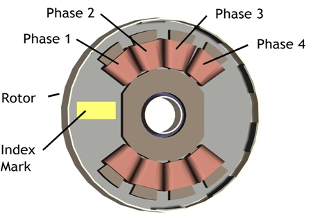
The whole motor is about an inch across, and maybe a quarter inch thick. There's not a lot of room inside. Fortunately, there isn't much in there. There's a mild steel stator that supports eight windings that make up the four motor phase windings. There's (hopefully) room for a reflective optical sensor for detecting the index mark on the rotor. The stator can be cut down from a standard flat steel washer. The rotor is thin gauge mild steel with ten equally spaced tabs around the edge. The tabs are bend upward and epoxied to a thin brass ring. The rotor turns on a short length of brass tubing epoxied to its center.

While the variable-reluctance rotor is easier to make than a permanent magnet rotor, it does require a more complex stator. With a permanent magnet rotor each stator winding does double duty. Because a winding can both attract and repel a magnet by reversing the current through the winding, a permanent magnet motor can get by with only two windings. Because a winding in a variable-reluctance motor can only attract the non-magnetized steel in the rotor, the V-R stepping motor needs four windings.
It operates like this:
With current going through the phase 1 windings, the rotor has a set of tabs lined up with the phase 1 stator poles. The phase 2 stator poles are half-way lined up with the adjacent rotor tabs.

When the current though phase 1 is turned off and current through phase 2 is turned on, the rotor turns counter-clockwise to align those tabs with the phase 2 stator poles. The phase 3 poles are now half-way aligned with a set of rotor tabs.

Shifting the current from phase 2 to phase 3 results in another step counter-clockwise, and setting the stage for the next step by partially aligning the phase 4 poles with another set of tabs.

When current shifts from phase 3 to phase 4, the motor steps again. At this point the rotor is positioned so that the phase 1 stator poles are partially aligned with a tab.

Shifting the current from Phase 4 to phase 1 brings a tab back into alignment with the phase 1 stator pole. The motor has taken four 9-degree steps for a total rotation of 36 degrees, or just enough to position the rotor to display the next digit printed on the outer surface of the rotor.

Yet Even More Air-Core Movement Hand Waving (27 April 2008)
It seems to work.
I completed a prototype movement with 1,000 turns of 38 gauge wire on each of the two windings. The rotor responds very quickly to 50 milliamps. I'm not sure if I'm seeing any problem due to shield remanence. If it's there, it's small. I'll need to put a longer pointer on the shaft to tell for sure. If there is a problem, an easy fix is to increase the diameter of the shield.
The shield used in this prototype is a 1-1/2" length of nominal 1" diameter thin wall electrical conduit ("EMT"). I try to use commonly available materials in my projects. EMT is sold at most home building supply stores. Galvanized steel fence post offers a slightly larger shield possibility. The smaller fence post material has a nominal diameter of 1-5/8", and is also commonly available.


There's more information about air-core movements on the Air-Core page.
Yet More Air-Core Movement Hand Waving (24 April 2008)
One thing I noticed with the larger (10 mm) air-core rotor magnet is a larger degree of eddy-current damping. When a magnet moves next to a conductive material, it induces electrical currents into that material. The currents generate magnetic fields which oppose the field of the magnet. If you have a (diametrically magnetized) cylindrical magnet rotating in a conductive tube, the induced currents and resulting fields act to oppose the rotation. The faster the rotation, the larger the opposing force.
This is a good thing.
If you have a gauge with low friction bearings and provide an abrupt change in the pointer position, the pointer will oscillate around the new position before settling down. This is annoying. To stop the bouncing, it's nice to have a force that opposes the motion and is larger as the motion is larger. Exactly what eddy-current damping does.
So, I decided to work more with the larger rotor magnets rather than with the smaller. The advantage of the smaller magnets is that the smaller fields would reduce the inaccuracy due to remanence problems with the shield. (see the 17 April section.) Since I'm using a large magnet, I'll use a larger shield to address the remanence issue.
The first shield was a short length of 1" nominal mild steel tubing. It actually turned out to have an innner diameter of 0.89". For the new shield, I'll use 1" thin wall electrical tubing. This has an ID of 1.05". I'm hoping that will make enough of a difference. If not, I'll just try something larger.
These new experiments use a metal on metal bushing rather than a metal on plastic bushing I started with. I'm trying a steel shaft rotating in a bit of brass tubing. I'm also only using one bushing in the new movements. The older movement had a plastic bushing at each end of the housing. The new movement does away with the rear bushing and simply lets the rounded end of the shaft rotate against the flat end of a brass plug.
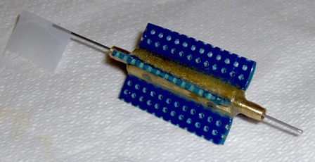
I'm trying two types of material for the shaft. The first is 0.031" diameter stainless steel spring wire. The second is a #7 basting sewing needle. The needle is nickel plated steel about 0.027" in diameter. Its surface is smoother than the spring wire, plus, it's easier to find. I'd prefer a larger diameter, but the smoother surface results in slightly lower friction.

I'm also trying a different construction technique. The brass tubing that acts as the bushing is epoxied into the movement body. I made an alignment tool (the brass item at the bottom of the picture) that holds the bushing while the epoxy sets up. This makes a huge difference in the time required to build a movement.
Air-Core Movement Experimenting (21 April 2008)
The air-core movement pictured below produces quite a lot of torque, as far as air-core movements go. This is primarily due to a very strong rotor magnet, a neodymium cylinder 5 millimeters in diameter by 10 millimeters long. The downside is that this magnet is strong enough to slightly magnetize the shield. This leads to a small, but measurable positioning error.
For this version, the shield is a piece of nominal 1" diameter mild steel tubing which I annealed with a small propane torch. One possible way to reduce the magnetization is to use a thicker and/or larger diameter shield. Perhaps a short length of 1" or 1-1/4" pipe would work.
What I actually chose to do was to use a smaller magnet.
I have some 4 mm diameter by 5 mm long cylindrical magnets, so I thought I'd give one of them a try. I'm also used a different construction technique. Rather than making plastic bushings and using stainless steel spring wire for the rotor shaft, I used brass tubing for the bushing and a polished chrome (nickel?) plated sewing needle for the shaft. I made a very rough prototype with only a single winding.
It works quite well. There is less torque due to the smaller magnet, but still enough to swing a balanced pointer. Because I was a little sloppy making this prototype, I need to rework it a bit before I can put the shield in place. So at this point I don't know how well using the smaller magnet reduced the shield magnetization.
Both approaches could do with a bit of refinement; however, I think either could form the basis of single-pointer, steam-gauge style sim instruments.
Book Progress and Air-Core Movement Experimenting (17 April 2008)
The joystick chapter has gone through a bit more editing and is sitting right at 34 pages. There are a few things wrong with it that I know of and undoubtedly several more that I don't, but I'm a little too close to it for further editing. I'll let it set for a while and come back later.
I had expected to go into building mode and construct the third (and hopefully final) prototype of the chapter project (a floor mounted joystick). However, I've gotten several emails from different people about air-core movements. Because of their interest and because I have been collecting material to do so, I decided, instead, to prototype an updated, new and improved, super deluxe, DIY air-core movement.
This air-core movement uses a cylindrical rare earth magnet for the rotor. Because this magnet has an axial hole, it's really easy to make the rotor. For the shaft, I used a length of stainless steel spring wire. It's not quite as smooth as some of the other material I've pressed into service, but it seems to work well, and it's a stock product. Here's what I ended up with just before beginning to add the windings:
After adding the test windings:

And after sliding it into a 1 inch diameter magnetic shield:

To be expedient, I only used 100 turns for each winding. On the finished product, I would expect to use somewhere around 1,000. As a result the sensitivity is only about a tenth of what it should be. That's okay. This is only a test prototype. I simply push ten times the current through the windings during testing. It's a heck of a lot easier to put 100 turns of relatively heavy wire on the assembly than 1,000 of really fragile, fine gauge wire.
The test performance is quite nice. Put current through the windings and the rotor zips to a new position.
The next step is to test for repeatability. A problem with air-core movements is that the rotor magnet can magnetize the shield. It's not a huge amount of magnetization, but it can be enough to screw up the accuracy. You minimize this by making the shield diameter large enough that it doesn't see much rotor flux, by making the shield thick enough that what flux does reach it is "diluted" in that thickness, and by using a shield material with low remanence.
Remanence is the tendency of a material to stay magnetized after being exposed to a magnetic field. Lots of materials have low or zero remanence, glass for example. Unfortunately, the vast majority of them suck at being a magnetic shield. The trick is finding a material that can shield without becoming magnetized itself.
Actually, that's not quite right. The REAL trick is finding an affordable material that can shield without becoming magnetized. Iron alloys with high nickel content (Mu-Metal, etc.) do a pretty good job. The problem is one of availability to hobbyists at reasonable cost.
So, the approach I've taken is to use annealed mild steel tubing with a relatively large diameter and medium thick wall. It has "low" remanence, and shields well enough, but I don't know how bad the remanence problem will be. So I will have to test for it.
Book Progress (8 April 2008)
The Joysticks chapter is mostly complete. At 34~35 pages, it's about 10 pages longer than expected. I added more illustrations than I had anticipated. Next step is to build another project prototype using the directions from the draft. I'm sure this will lead to a number of tweaks.
Oh, I also scanned the book 2 page while thumbing through the manuscript. The book 2 page now accurately reflects progress to date on the book.
Book Progress and Air-Core Movement Thoughts (31March 2008)
I have a fairly rough pass though the project portion of the joystick chapter. I dumped a lot of words down and left placeholders for illustrations. Then I went into TurboCAD and started drawing. As the illustrations came together, the word dump began to look a bit, well, dumpy. So now it's time to go back into wordsmith mode and make things a bit less so. When I go through the text I'm sure I'll find places where the illustrations don't quite convey all that's needed, so I'll end up back in drawing mode. Hopefully the process will converge.
Since book 1, (Building Simulated Aircraft Instrumentation), came out, there has been a surge of retail sources for magnets of all shapes and sizes. Of particular interest are cylindrical magnets that are magnetized through the diameter rather than through the length. And of extra special interest are those cylindrical magnets that have an axial hole. Magnets of this sort lead to thoughts of rotors for air-core movements. I haven't had a chance to build a prototype, but I think you could make an air-core movement something like this:

The gold cylinder is a neodymium magnet from The Super Magnet Man. I'm confident this will work, thought there is a question about the overall dimensions. The neodymium magnet is extremely powerful and may partially magnetize the shield, the outer gray cylinder. Magnetizing the shield leads to positioning error, so it needs to be minimized. You do this by making the shield thicker and larger in diameter, as well as, choosing the right material. Well, the best material costs too much, so the old standby, annealed mild steel will have to do. I'll make a SWAG of 1" OD mild steel tubing with 0.050" wall thickness as a starting point.
A Bit of Book Progress (7 March 2008)
Believe it or not, this is actually the heart of a low-cost uber-quality floor-mounted joystick. It's the project for the first chapter. Most materials are sourced from Home Depot (a local big-box building supply store).
I'll be using a pair of the Bourns 6639 potentiometers for position sensors. The more I rigorously test the Bourns pot, the more I like it. It has tight mechanical specs and requires little torque. I expect the completed project to be very responsive.
The Ultimate Potentiometer? (6 March 2008)
When I build project prototypes I typically dig through piles of stuff in my garage looking for materials. Collected over years of attending California swap meets, this stuff will eventually cause my executor great heartburn, though hopefully many years from now. The problem is that using this stuff occasionally causes me heartburn in the here and now.
Once the prototype has proven the concept, I have to document the project. I can't make a parts list full of obsolete mil-spec parts from my garage. I have to list parts that you can actually buy without going broke. Sometimes this is hard to do.
As I am working though the Nth version of the project for the Joystick chapter, I have to come up with a suitable potentiometer part number. You're probably aware that most moderately priced pots are not up to the challenge of being used in a flight sim joystick. They wear out too soon.
I've written about pots in general to give readers the background needed to make an informed choice. (Here, for example.) However, when writing a book, and especially when describing a specific project, it's a really, really good idea to refer to a specific part number. So, I was very pleased to come across the Bourns model 6639 series of potentiometers. (Bourns 6539/6639 spec sheet.)

This has a no-load rotational lifetime spec of 10,000,000 rotations. "No load" means not putting significant lateral or end-loading forces on the shaft, just carefully turning it. For comparison, a standard, hobby-quality pot will have a lifetime of 30,000 to 50,000 rotations.
The Bourns pot isn't exactly cheap at US$11.40, but I think it hits a sweet spot: excellent performance at a price that only makes you wince rather than scream. Precision pots with good lifetime specs mostly start out with a US$20~30 price tag.
This pot is stocked by Mouser and Digikey.
Income Tax (7 Feb 2008)
Arrrrgggggh!
Joystick Chapter Progress (5 Feb 2008)
I have a pretty good draft of the text portion of the joystick chapter. Next step is to write the project directions and draw the project illustrations. I've already designed and built two prototypes of the project, but by the time I finish with the drawings I will have made changes. So I'll end up building a third prototype to verify the instructions in the chapter.
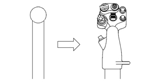
This is just a bit of doodling to illustrate the point that joysticks have evolved.
Playing with Illustrations (1 Feb 2008)
This is an intermediate step along the way to developing a drawing that shows the key principles of electric control loading. The final drawing for use in the book will a black & white line drawing, but it's fun to turn on the colors and 3D modeling along the way.

Writing and Drawing (30 Jan 2008)
Laid down a fair amount of text and started the illustrations for the Joystick chapter. It's starting to come together. My original thought was that there wasn't really all that much to say. Joysticks are such an integral part of computer game play that there are many choices for off the shelf sticks. Why waste time building a joystick for your sim when you can just buy something and move on to projects that don't have a good purchase alternative? I thought the joystick chapter would be a soft introduction to the book and the home built flight sim hobby. I was wrong.
Turns out that how much effort you put into a joystick depends on what aircraft you want to simulate and the fidelity you're looking for. If you happen to be building an F-16 sim, the cougar's pretty much the stick of choice. But, even it can be improved. Out of the box, the cougar is a motion activated stick. The F-16 side stick controller is a force activated flight control. If you want a really good F-16 sim, start with the stock cougar. If you want an outstanding F-16 sim, finish up with a force sensing mod to a cougar. But, if you're not building an F-16 sim, life gets more interesting.
If you're looking for "okay" simming of A/C with sticks, there are fair choices on the market. Buy one and get on to building an instrument panel or a set of pedals. Moving beyond the just "okay" requires more effort. You need to do some research. What does the real stick do? Will your simulation application support those functions? Can you add the missing functionality? Is it worth it to you? What does the real stick feel like? What does it look like? And so on, and so on.
So the joystick chapter will contribute more than I originally expected. It's still an introduction to the book and to the hobby, but it's also a guide to boosting the flight sim experience by doing the joystick right.
Writing, for real (27 Jan 2008)
I've actually been able to spend some time putting together new words rather than editing old words in Book 2. I'm working on the first chapter which covers joysticks. I'm not sure this should be the topic for the first chapter, but certainly I need to cover joysticks somewhere.
Maybe the first chapter should cover the overall approach to building a simulator. No, not enough material to justify a complete chapter. If I turn it into a full chapter, it'll be too philosophical and no one will read it. The overview fits best in the Introduction. Oh, but, nobody reads the introduction either. Oh crap, I think I'll just go back to writing about joysticks.
Using Real Instruments chapter updates (22 January 2008)
I've updated the Using Real Instruments chapter that contains the DTS project. I'm sure there's room (and need) for a few red editorial marks, but for the time being, it's looking pretty good.
DTS v2.0 & Free Programming Resources (20 January 2008)
The revised version of the Digital-to-Synchro converter is together and is apparently working. (No smoke, anyway.) I'll do a little more testing, but I don't expect problems.

Each version of each project suggests a follow on version. This project uses linear power amps to buffer the synchro output voltages. These amps require a bulky heatsink. So, this gets me thinking, what if I used switching ("class D") amps instead? Might be able to do without a heatsink, or maybe just a little one. Then I remember, I've got a few thousand other things I need to do too. Sigh! Gotta stop somewhere.
*****
Programming skills are extremely useful. Being able to write fairly simple programs and interface them with other sim applications can gain you admittance to the pantheon of sim greats.
An overstatement?
No.
If you have no programming skills, you're at the mercy of those who do. You use applications as they are out of the box. If the applications do what you need them to do, that's great. If not, well... suck it up, buddy.
On the other hand, if you do have a bit of programming knowledge, people smile when you enter the room. They're polite. And, best of all, you can add to your sim setup so it does what you want it to do.
Surprisingly, you don't have to be a real wizard. You're not building life critical systems for international deployment on multiple hardware and software platforms. You're building a application or two to run on your computer for your own amusement. All you need to be is a moderately successful amateur.
Many tools and tutorials are free. Since I focus mostly on Microsoft Flight Simulator, I'm going to point to a couple of MS resources.
First of all, you can get a compiler and development environment for free from MS. You can go with Visual C++, Visual C# and/or Visual Basic. I recommend VC++ as it's easiest to use when interfacing with MSFSX. You can use C# and Basic as well, but you'll have a couple of additional hurdles to jump. You can download the express edition of MS Visual C++ here: http://www.microsoft.com/express/vc/
MS also offers several tutorials on using VC++. For starters, There's the "Introduction to Visual C++ 2008 Express Edition" here: http://msdn2.microsoft.com/en-us/beginner/bb964629.aspx
There's actually an entire learning center here: http://msdn2.microsoft.com/en-us/beginner/default.aspx
"Coding 4 Fun" is a Microsoft hosted blog (http://blogs.msdn.com/coding4fun ) where non-MS software types post tutorials. Of particular interest is the series, "Beginning Game Development" by Derek Pierson. It provides a nice introduction to DirectX. DirectX is the Microsoft API (application programming interface) for game development. Basically, it gives you the means to create complex dynamic imagery, to interface with the sound card, and to connect with the keyboard and mouse.
Finally, don't forget that SimConnect, the API into MSFSX, is documented in the SimConnect SDK which ships on the installation DVD of the deluxe edition of Flight Simulator X.