
CNC Project (21 Dec 2012)
Warmer weather hasn't arrived, but at least the emergency stop switch has.

This is a mechanically latching push button. Push the red button in and it stays in until twisted clockwise. It has one set of normally open contacts and another set which are normally closed. This will be wired into the motor controller such that when pushed, it kills power to the motors. It's useful because CNC machines don't have undo commands. When you see a mistake playing out, a big red button in an easily accessed location is the fastest way to limit the damage.
This particular switch comes from China care of Ebay. In a true industrial application you'd see an expensive, mostly metal switch capable of surviving a great deal of abuse. This one is mostly plastic, and cost less than a good cup of coffee. It's by no means "industrial", but it should work well in my much more benign application.
CNC Project (11 Dec 2012)
I've managed to get a halfway reasonable color coat on the base (with an emphasis on "halfway"). What with cold weather and the occasional scratchy throat from dust, I rushed the priming and sanding. I covered the wood grain, but am left with rather too obvious brush strokes from the primer. Sigh.

The cover is not yet painted, and probably won't be for some time given the cold weather headed this way.
Masks (9 Dec 2012)
I've been doing a lot of sanding of both bare and painted wood. While my workspace isn't heated, it is enclosed, and the amount of dust in the air can increase far beyond the comfort level.
I've been using "N95" disposable dust masks, but lately I've still ended up with a scratchy throat after a sanding session. I finally took a closer look at dust mask options.
"N95" is a rating. The "N" indicates that the filter media is not oil resistant. An oil resistant mask would have a "P" rating, while an "R" would indicate the media to be oil proof.
The numerical portion of the rating is the percentage of particulates removed in a standardized test. There are "95", "99", and "100" ratings. The "100" rating is actually rounded up from 99.97%.
So, my N95 masks were maybe removing 95% of the dust. I say maybe because I don't know how the range of particulate sizes in the rating tests compare to the actual sizes in my work area. Another issue is that disposable masks don't seal well to the face. Leakage around the mask edge is not filtered at all. N95 masks clearly remove some dust, but given my scratchy throat, a non-trivial amount gets by.
I decided to try something better, so I bought one of these.

It's designed for lead and mold spores as well as nuisance organic vapors like paint thinner. The "P100" means it's blocking just about all particulates. The plastic body seals tightly, and it's got one-way air valves for controlling air movement through the filters.
WOW! What a difference! No more scratchy throat.
Recommended.
CNC Project (5 Dec 2012)
The weather continues to be uncooperative, cold, and rainy. It's not just making it difficult to paint. It's also pulling my attention elsewhere, to gutter cleaning and other similarly unpleasant activities.
At least the few remining parts are drifting in. Here are the follower nut and coupler for the z axis acme threaded rod, the motor shaft pulleys for the x axis and y axis, and a few of the limit switches. I'm still missing the emergency stop button, and perhaps a few other items.

CNC Project (26 Nov 2012)
Progress has slowed due to low temperatures in my unheated work area. I need to get at least the base painted before assemblying the metal pieces, and painting places a limit on how cool the shop area can be. The first assembly steps involve bolting the rail supports to the two sides of the base. I really don't want to be in a position of trying to paint around the metal portions come Spring. So far I've managed to get most of the base primed.

CNC Project (20 Nov 2012)
The motors and associated electronics arrived from CNC Router Parts last night.

Shipping had been delayed because the motors had just gone out of stock when I placed my order. Communication with CNC Router Parts was excellent. They let me know what was going on and I have no complaints. The delay hasn't slowed the project as I'm still involved with finish work on the base and cover.
So, here's what's in the box:
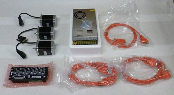
Three 380 inch-ounce stepping motors, a 48 volt power supply, a Gecko G-540 stepping motor driver, and three motor cables.
CNC Project (16 Nov 2012)
The cover now looks like a cover. It's missing the back, but that's an easy addition. Once that's in place I'll cut the cover into two pieces. There will be a hinge just behind the top window so the front portion of the cover can be lifted to provide access.

CNC Project (13 Nov 2012)
I'm currently assembling the cover. It's been time consuming because there are four window openings and the glue-ups need to be staged. Two of the window openings have a corner radius larger than my largest hole saw. I had to cut the corner curves by hand with a coping saw. Not my best work, so more time went into cleaning up the results. Now that I'm finally to the point of gluing the pieces together, I need to do it step by step to make sure alignment is good.

CNC Project (9 Nov 2012)
The CNC base is structurally complete. I still have a few days of finish work to do, but that can wait until I've assembled the cover.

I've ordered the motors, power supply, and motor driver (a Gecko G540) from CNC Router Parts. The cost is higher than many of the Chinese options on Ebay, but based on the comments I've seen in CNCZone threads this seems to be a case of getting what you pay for, or perhaps more to the point, not getting what you don't pay for. I'm confident in my ability to make any of the options work, but my goal in this project is to learn CNC, not troubleshoot potentially iffy electronics to save a few bucks.
Unfortunately, the motors just went out of stock, and it will be at least a week before they get more. Given the time required to assemble the cover and do the finish work, that shouldn't be a problem.
CNC Project (6 Nov 2012)
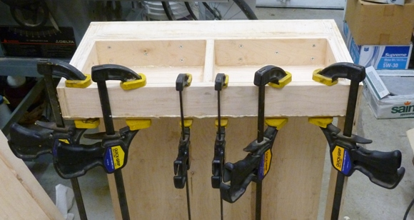
Gluing is progressing. This picture shows the base on its side on the floor. The clamps are holding the top edge of the inner left sidewall. The other edges are held by finishing nails while the glue sets. The top edge is chamfered so nails don't hold so well there.
CNC Project (2 Nov 2012)
I've glued the the top surface onto the base structure. This forms the floor which will ultimately support the spoil board and the materials being machined. I've also finished most of the structure which forms the front, back and walls. These components are simply being dry fit. I'll glue and screw them in place over the next day or so.
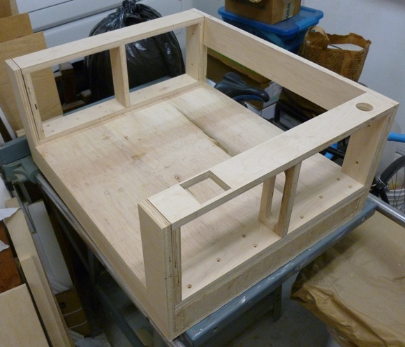
The pieces were cut from plywood with a nominal 3/4" thickness. It was actually sold as 3/4" plywood. It's close. I measured it at 23/32". This resulted in a few dimensional errors that I corrected for. The error(s) that I didn't anticipate result from the two sheets of plywood used as source material having different thicknesses. Silly me thinking that they would be the same.
CNC Project (29 Oct 2012)
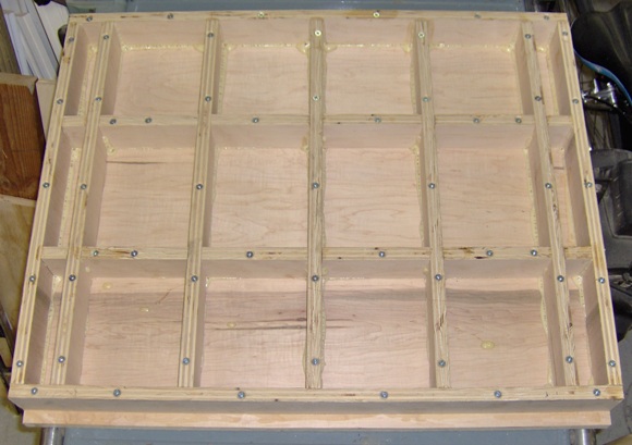
The remaining ribs are in place in the base.
CNC Project (28 Oct 2012)
I've started to assemble the plywood case for the unit. This picture shows the stiffening ribs internal to the base. This may seem like overkill, but rigidity is critical to accuracy. If you expect to hold tight tolerances when you fabricate a large item, the machine doing the cutting must not flex regardless of the load on the spindle.

CNC Project (24 Oct 2012)
The CNC router metal components are supported by a U-shaped structure made from plywood. Plywood is one of the more dimensionally stable wood building materials, significantly more so than straight lumber. Plywood offers a good balance between strength, stability, and weight. This project uses the better part of two 4x8 sheets of 3/4 inch plywood. The structure is engineered for extra rigidity.
At this point I have just about all the plywood pieces cut. A few holes, notches, and trimming remain before I begin to assemble them.

I'm beginning to realize how heavy this thing is going to be.
Pull Switch (21 Oct 2012)
While toggle, push, and rotary switches are the most common types you're likely to need in flight simulator building, pull switches do occasionally make their appearance.
Finding a suitable pull switch can be problematic. The fill disable switches on the A-10 fuel panel, in particular, fall in this category.
Recent discussions on the Eagle Dynamics Home Cockpit forum centered on this and an automotive pull switch was suggested. The switch looks good in the picture on the vendor's site, but the site provides only limited information. Since the vendor is Pep Boys, an automotive parts store with a store near me, I decided to pick up a switch for closer inspection.
The switch is a medium quality Chinese import which will likely work well in a simulator. It mounts in a 5/16" hole, has a single set of contacts, and provides decisive tactile feedback when pushed or pulled.

The switch is 1.2" at its widest. The overall length is 1.8" when pushed in. When pulled out, the switch gains another quarter inch.

Rotate the switch 90 degrees and the width is only 0.85".

The switch grip easily unscrews from the switch shaft. The thread appears to be metric. The grip differs from the actual A-10 switch grip, but it looks easy enough make a more realistic replacement.

CNC Project (17 Oct 2012)
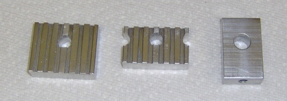
Here are a few recently completed miscellaneous parts, two belt clamps and a belt tensioner.
The metal work is almost done. There are a few limit switch mounting brackets, which should be relatively quick to make once I have the switches and know what size the brackets need to be, and the router mounting brackets, which will probably take quite a while since they are to be made from 0.75" thick bar stock and I don't have a metal-cutting bandsaw. I'll have to drill a series of holes and file the edges smooth.
CNC Project (14 Oct 2012)
There are a number of wires that run to the gantry and carriage. They power the router, the z axis motor, and connect to several safety limit switches. These wires are supported by an articulated arm assembled from these parts (along with a few bearings, not shown).
They go together roughly like this.

The small block in the rear left will fasten to the inside of the enclosure while the free end of the arm in the foreground will pivot on a bearing mid span on the gantry.
CNC Project (11 Oct 2012)
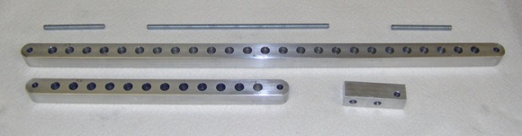
These are z axis rail parts.

They fit together like this.
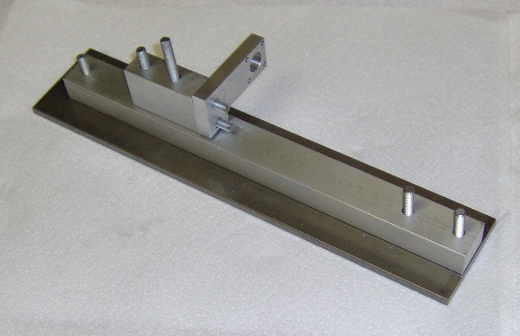
The router mounting brackets will be supported by the two studs on the right. The little arm is the nut plate that the acme-thread antibacklash nut bolts to. The acme rod that will pass through the nut will produce the z axis movement.
This entire assembly will be mounted in the carriage.
CNC Project (9 Oct 2012)
I made the z axis motor mount pieces. They're not quite perfect, but I think they'll do the job.

And here they are in position on the carriage assembly. I don't have the motors yet, but perhaps I'll dig around and see if I have a NEMA 23 unit I can use to check fit.

The z axis rail and router mounting clamps are the biggest remaining bits of metal work. There's also an articulated arm which supports the wiring going to the carriage. Once that's behind me I'll move on to the wood enclosure. Oh, and at some point I have to make some brackets that will support the limit switches. I'll have to get the switches to determine the appropriate mounting hole patterns.
CNC Project (5 Oct 2012)
A few more parts completed...

And the carriage begins to take shape...
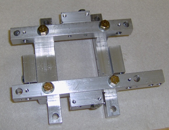
The carriage assembly as shown is missing the z axis motor mount, the y axis belt clamp, and most importantly, a great many bearings. The empty large holes will be filled with the bearing axis bolts. There are a lot of bearings because the carriage supports itself on the y axis rail while also supporting the z axis rail.
Next: motor mount and belt clamp.
CNC Project (4 Oct 2012)
A little more progress, a few more parts. These will go into the the carriage assembly.

These parts have lots of holes, each requiring accurate placement. I use a few basic tools and get good results.
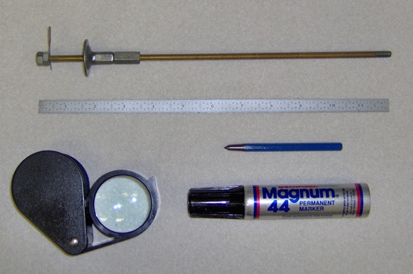
The key is an accurate machinist's rule. The one in the picture has fractional inch markings by 64ths on one side and decimal markings each .01 on the other. I don't use the rule to mark directly on the work piece, however. I use the rule to set the distance between the scribe and fence of a marking gage.
I made a marking gage from a length of threaded brass rod. The fence is a fender washer epoxied to a coupling nut. A second coupling nut serves as a lock by jamming up against the first when I've set the fence where I want it.
The scribe point is an old sewing machine needle donated by my wife. It passes through a hole drilled in the brass rod and is held in place by a pair of nuts.
It's surprisingly easy to set the distance between the scribe and fence to match one of the rule markings. With a little care, the scribe can be set very nearly equally between markings. So, using the decimal side of the rule, you can set the marking gage to within .005". If your eyes aren't quite up to that challenge, and mine aren't, that's where a magnifying lens comes in handy.
Once the marking gage is set, you can scribe a line on the work piece. To make the line more visible you can paint layout fluid on the piece first and then scribe. As an alternative to layout fluid, you can use a large permanent marker.
Hole centers are located by pairs of intersecting scribed lines. Getting a drill bit to make a hole there is a lot easier if you center punch the intersection. I use a basic center punch and a hammer rather than a spring-loaded auto-punch, because this allows me to make a light punch mark and check my accuracy with the magnifier. If I'm off, I can easily correct.
CNC Project (28 Sept 2012)
A few more parts are done so I've been able to partially assemble the gantry.
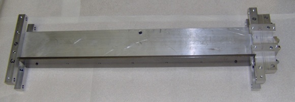
The arms on the gantry ends will support the bearings that ride on the x axis rails. The bearings are low cost roller skate bearings, but are nonetheless tight tolerance ABEC 7 units. Their use is one of the cost saving aspects of the design. V-groove bearings and rails could have been used here, but at a much higher cost. The tradeoff is more bearings and metal work.
The darker metal spanning the front of the gantry is the steel y axis rail. It will support the carriage which will be moved by a stepping motor mounted vertically on the right end of the gantry.
Next up: making the carriage.
CNC Project (25 Sept 2012)
As you might guess from the number of holes in the first six pieces I spoke of last posting, there are a lot of bolts used in this project. I could probably have found most of them at a local big box home builder's store, but I'm lazy. Instead, I ordered them from the Bolt Depot and, even with shipping, I think I paid less.
Well, yesterday a box showed up fill with an impressive assortment of plastic bags of nuts, bolts, washers, and so on:

Each bag has a label with a picture and a description. I suppose this makes fulfilling the order less error prone; I find it a nice touch on the receiving end as well.

I've managed to make a few more parts. These are the larger parts that will make up the gantry. The gantry supports the y axis rail.
CNC Project (21 Sept 2012)
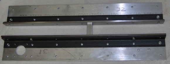
I've completed the x axis rails. There are only 6 pieces here, but the total of 78 holes resulted in a time-consuming fabrication. Also, 14 of the holes had to be threaded.
CNC Project (15 Sept 2012)
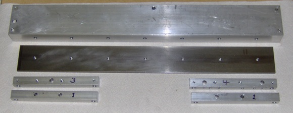
I've made my first important milestone on the CNC project. I've cut the metal bar stock to length.

Part 31, in the lower left, is 24 inches long; this will not be a big CNC machine. The work area will be 16 inches by 16 inches with several inches of vertical spindle movement. I expect to be able to make panels and instrument components, but much of the value is in the building and teaching myself about CNC.
HMDs Becoming Hot Again, CNC (11 Sept 2012)
Every now and then a consumer grade head mounted display appears on the market or at a trade show. Then it just fades away. It looks real shiny initially, but for one reason or another HMDs have no staying power. The Oculus Rift HMD aims to change that.
The Oculus intends to push video game immersion levels high enough that HMDs become a standard component of high end gaming computers. That will be hard to do.
Good immersion demands that the imagery be not only high resolution , but highly reactive as well. When you turn your head, what you see should change instantly. Any response lag will reduce the immersion. Not a trivial task.
Oculus has just completed a kickstarter campaign to gain funding for the project. The goal was $250,000. The campaign raised $1,600,000. Apparently there's a lot of interest in a well done VR HMD.
If you're interested in following their progress you can drop in on the Oculus website, as well as, the "Road to Virtual Reality" blog.
On to a different topic:
I'm building a small CNC router based on the Momus CNC plans. It's a well engineered desktop system that's suitable for making instrument parts and backlit panels. Currently I'm fabricating the metal components. I'll post a few pictures once I've made a bit more progress.
Slow Summer (26 Aug 2012)
Yep, slow.
Plumbing, Reading, a Little Writing (3 July 2012)
There was a minor leak in the upstair bathroom. Minor, except that it wasn't obvious until we noticed bubbles in the ceiling paint of the downstairs bathroom. Apparently the wax ring under the toilet did not seal properly. By the time we became aware of the problem we had some minor damage to the upstairs sub-floor to complement the ceiling damage below. Not a lot, and easy enough to fix, but doing so required cutting into the vinyl flooring. Well, of course, there was no desire to patch the vinyl. Better to treat this misfortune as an opportunity to move up to ceramic tile, which meant shopping for said ceramic tile. And, come to think about it, the toilet, the source of that offending leakage, was never really popular, so, of course, while we're shopping, why not look for its replacement as well...
sigh!
I've been rediscovering the science fiction of the late Charles Sheffield. Great stuff!
And, bit by bit, I'm continuing my quest to write an understandable and comprehensive chapter about projection systems. My current focus is screen directivity. A screen must disperse light for the image to be seen, but little of the projected light actually makes its way to the viewers' eyes. Far too much of the light can end up hitting the screen a second time where it ruins contrast. So, broad dispersal of light means broad viewing angles and minimal directivity, but controlling directivity and restricting viewing angles can be an approach for improving contrast. Writing about projection systems is, it seems, largely about making the reader aware of trade-offs.
Chapter 3, Book 3 (13 May 2012)
Okay, so I'm now making the third pass through chapter 3. Or is it the fourth? I'm not really sure.
You've probably picked up that this isn't just a grammar and spelling issue. The problem is making the chapter less like an encyclopedia and more like something people would want to read.
This is the chapter on projection systems. You know, a screen, a projector and a dark room then you're golden. Except maybe not. The goal isn't simply to create an image, it's to create an image which strongly supports depth of immersion. Plus, the book's aimed at wildly creative, diverse bunches of readers: flight sim addicts, first-person-shooter zombies, motor sport crazies,... really anybody wanting to lose themselves in a computer generated virtual world, (my kind of people). So who says there will only be a single screen and projector? Will the screen(s) be flat? Will the imagery be 3D or collimated?...
The issue is answering all the questions coherently.
Mike's Tips Article (1 May 2012)
Just finishing a new Mike's Tips article for posting at MyCockpit.
Only One Copy Left (29 April 2012)
After filling all outstanding book orders I find that I have only one (1) copy of Building Simulated Aircraft Instrumentation left.
I won't reprint the book. There are enough changes I want to make that I prefer to develope a new edition... Assuming there's enough interest, of course, and that I finally manage to complete book 3.
Update: 8:10 PM (pacific time) The last copy was just purchased. BSAI is out of stock.
CNC (24 April 2012)
Bits and pieces for the CNC project are drifting in. The plan revisions aren't yet available, though an updated bill of materials is. The BOM also lists the lengths of the individual pieces rather than just the total for each size of metal stock. So, while I don't yet have the revised plans, I can at least cut the individual metal pieces to length.
This has been a good opportunity to excavate my work area in the garage. Apparently certain unnamed family members have seen my recent lack of work there as license to turn the space into a storage zone.
HA! Won't they be surprised!
CNC (9 April 2012)
I've been looking into small CNC machines for quite some time. I had thought I'd pull a design together myself, but ran across a very appealing set of plans. The "Momus CNC design" appears to offer good performance from a relatively low cost design. It will handle wood, plastic and soft metals.
Check out this YouTube video.
There's a support forum on CNC Zone.
I waffled a bit, but after watching the videos several times I bought a set of plans as a PDF download. First thoughts: A professionally presented, well thought out design well worth the $20.
And then I found out that a revised version is on the horizon. Fortunately, the designer, Bob Pavlik, will be making the revised plans available to buyers of the current version.
I'm looking forward to them.
New Mike's Tip Article (31 March 2012)
I completed a new Mike's Tips article. It's a brief intro to force sensors for use in simulators. It should be posted soon over at MyCockpit.
Punching Out (4 March 2012)
My neighbor recommended the book, Punching Out, edited by James Cross. It's a collection of stories, mostly first hand acounts, of ejections from high speed aircraft. If you have any interest in military flight, this book will hold your attention.

New Mike's Tips Article (28 February 2012)
Just sent off an article on electromagnetic head tracking for posting over at MyCockpit. Should be posted in a day or so.
Most head tracking that we use in the hobby world is based on optical means. We've got commercial units like TrackIR and open source ones like FreeTrack. They use webcam video and image processing which places a burden on the host computer, burning cycles that could go toward rendering the game imagery.
Most military head tracking systems are based on electromagnetic fields and use a local processor. The arrival of low cost micro controller development systems like Arduido and chipKIT place this technology within reach of the hobbyist.
Potentially, one could have fast, accurate head tracking with no processing required from the host computer.
Still Beating on Chapter 3 (20 February 2012)
Chapter 3, Projection Systems, is the largest chapter, and I am not happy with it.
The chapter is large because there are many choices you can make when setting up a projection system: screen size and shape, gain, front or rear projection, mirrors or no mirrors, number of projectors...
I'm not happy with the current version because I want a more intuitive flow in the reading of it. I don't want a huge data dump, but there is so much interrelated material that it's in danger of becoming just that.
The key, I think, is following image quality through the system and showing how each design choice impacts the factors which support depth of immersion.
DIY Spot Photometer (4 February 2012)
A portion of the Projection chapter in book3 deals with projection screens. These are system components that you might want to build rather than buy, particularly so when your consider the prices of custom curved screens.
That begs the question of how to measure screen performance. When you can choose between screen fabrics, screen paints, and even flat wall paints, how will you know which is most cost effective or even suitable? You can't simply look at a screen sample or test panel. The human eye is a wonderful bit of highly adaptive optics, but that very adaptability means it's terrible for making objective measurements. To make objective choices you need the proper tools.
Screen performance is generally made using a spot photometer on a test jig that holds the screen sample and photometer in various controlled alignments. It lets you swing the photometer so the amount of light leaving the screen sample at different angles can be measured.
Reality intrudes: even cheap spot photometers are expensive.
I've done some work with an inexpensive luxmeter and a tubular light baffle to make crude spot measurements, but I've been thinking about improvements. A luxmeter is a basic light meter which measures ambient light levels. A spot photometer is a light meter coupled to a lens system that allows the luminance of a well defined portion of an emitting surface to be measured accurately. Adding a light baffle to a luxmeter does allow you to measure light leaving a surface, but the basic construction of the luxmeter greatly limits sensitivity, and you can just forget accuracy.
I started looking into building a spot photometer from scratch. The electronics is trivial, so I didn't expect any problems there. The optics didn't need to be anything special. The lens won't be forming a high resolution image. Its purpose is to collect light and direct it to the light sensor. Then it occured to me that DIY from scratch wasn't needed. I could just hack a cheap luxmeter.
So I bought an LX1010B luxmeter for about $15 through Amazon. I also bought a few other things to push the total above $25 so I could get free shipping. (I'm not cheap, just frugal.) My only real concern was that the luxmeter might be glued together. Fortunately, it turns out to be assembled with screws.
Here's the luxmeter:

And here's what's inside the sensor pod:

The small black square is the light sensor. It's a large area silicon photodiode. The green square in the center of the black circular cover is, I believe, an infrared rejection filter. All in all, it's pretty simple. The bulk of the electronics is in the other pod.
My next step is to add a lens. I'll try a 10x loupe I've ordered through Ebay for a few dollars. There's nothing special about it. It's simply a commonly available item which I can press into service collecting light for the sensor.
Back to writing for the timebeing.
Progressing (slowly) on Projection Chapter (29 January 2012)
I've revised the first third of the Projection Systems chapter. The first draft had a lot of good material, but didn't provide enough guidance through the process of developing projector performance requirements from display system goals. I'm fixing that.
Cost of Shipping Goes Up (24 January 2012)
The US Post Office has raised the cost of Priority Mail and Priority Mail International, the services I use to send books. The shipping costs on the book order pages have been adjusted to reflect this.
Sigh!
Book 3 and a New Mike's Tips Article (22 January 2012)
Chapter 2 is in a lot better shape overall, but still has a few rough spots. I'm not having much success smoothing those out currently, so I've moved on to chapter 3. I'll be revisitng chapter 2 later.
Chapter 3 is about projection systems. I moved some of the material into chapter 2, and some other material will shift into an appendix. The chapter won't necessarily become shorter because I'm adding additional material.
I sent off another Mike's Tips article to MyCockpit which will be posted soon. This one's on information sources for aircraft control panels like those found in the side consoles of military aircraft. Dimensions, fonts, colors, and so on are the topics of endless questions on forums. As it turns out, these are also the topics of several military standards which are in the public domain. If you know where to look, it's all spelled out.
Book 3, Chapter 2 (12 January 2012)
Still working on chapter 2 of Building Simulator Display Systems. I completely revised the chapter which improved it a lot. I just don't think it improved it enough, so I'm back at it.
The key issue is how much technical detail should be in it. Some readers see detail as something that boggs them down. Others like detail. Ultimately, the guiding principle is that there needs to be enough technical information in this chapter so that the following chapters make sense. I just have to present the material so the essence comes though without turning readers off.
The current revision feels too sparse. I'm in the process of adding additional detail, but structured so the extra detail can be skipped by bog-prone readers.