
Writing (5 December 2010)
Mostly writing these days. I have a draft of a new Mike's Tips article for MyCockpit covering contrast enhancing front projection screens.
New Article at MyCockpit, and a Hobbyist-Built Collimated Display (22 November 2010)
My latest Mike's Tips article has been posted over at MyCockpit.org. It covers depth of field in projection systems, something useful to know if you plan on using a curved projection screen. Why would you want to do that, you ask. Well, perhaps you want to build a collimated display system, just as Gene and Wayne have. They have posted pictures and Youtube links at several flight sim forums including MyCockpit and SimHQ. Well worth checking out.
More on Collimated Displays (25 October 2010)
I thought the chapter on collimated displays would be short and to the point: list the facts, point to some references, and be done. It hasn't quite worked out that way. I'd write a bit, have to research a bit more, and that would expand the chapter outline, which meant more writing, and research, and so on. The chapter's up to 35 pages and could stand as it is, but it also looks like it could grow some more.
There's been strong interest on the topic over on the MyCockpit forum. This resulted in me writing a Mike's Tips article on collimated displays. The forum interest continues to grow and looks like it will result in a viable DIY collimated display system.
Check out the MyCockpit thread.
Writing, Researching Collimated Displays (26 September 2010)
Still working on the collimated display chapter of the perhaps Book 3.
New Mike's Tips Article (16 September 2010)
Just sent off a new Mike's Tips article on rotary encoders to MyCockpit.org.
Collimated Displays (8 September 2010)
I have a sloppy draft of a section describing collimated display systems, what they do, and how they work. I've been surprised how much can be done with simple ray tracing and high school geometry. Also working with TurboCAD on supporting illustrations.

Collimated Displays and Binocular Vision (27 August 2010)
I'm revisiting the the topic of collimated displays. These are the display systems that supply the through-the-window views for high-end commercial flight simulators. They create a virtual image "at optical infinity", and in so doing, remove binocular depth clues. This is a good thing, because there are no binocular depth clues in the imagery. At least, there are not supposed to be. Problems surface when the imagery is displayed on an "optically close" screen. Normal binocular vision is pretty good a picking up this fact and the viewer correctly identifies the image as A) nearby, and B) 2-dimensional.
Turns out that these are not the reasons that civil aviation authorities mandate the use of collimated displays. They do so because non-collimated displays provide incorrect and different visual clues to the crew due to the difference in their seating positions.
Not being a civil aviation authority (or, according to my wife and daughters, any kind of authority at all) I'm interested in collimated displays because it can make an image appear to be A) not nearby, and B) not necessarily 2-dimensional. A physically small collimated display system can produce imagery that feels big, and because it suppresses the predominant human depth perception mechanism, binocular perspective, it allows weaker, monocular depth clues to surface. The result is more realism and depth of immersion.
Most of my current effort is going into ray tracing, a simple, but surprisingly useful tool for analyzing optical systems. Although ray tracing as generally applied is an approximation that rapid accrues error as the ray angles grow, spherical section mirrors have some properties that appear to allow accurate ray tracing.
Sent in the Article, Researching LCDs & PDPs (17 August 2010)
Made a few editorial tweaks to a new Mike's Tips article and sent it off. Should be up at MyCockpit in a day or so.
I've been researching LCDs and plasma display panels.
And, like everybody else, I'm curious what we'll finally see come out of the Microsoft game studio for "Flight".
New Mike's Tips Article Drafted (8 August 2010)
I now have a strong draft for another Mike's Tips article for MyCockpit. It's an overview of how easy it is to have professional printed circuit boards made. It'll be posted mid month.
Book 3... Maybe (2 August 2010)
Scenery display has a profound impact on how immersive the flight simulator experience is. In fact, we can say that for just about any game application; motor sport games are better with better graphic display, so are first person shooters, and so on. Having a great display system supports a great gaming experience.
That's where the idea for a possible third book came from. We're seeing more and more neat technology: better projectors, better big screen monitors, stereoscopic displays, butt kicking video cards,... What seems to be missing a guide to help choose, set up, and optimize.
I've been collecting and organizing material for several months. The material is shaping up into complementary piles that are beginning to resemble chapters.
Options & Planning overviews the major choices one might make when developing an uber-class visual display system. The idea is to take total control of the visual field and promote total immersion. Moving from the generic to the specific is where planning comes in.
Background is the information necessary to cut through the marketing crap. The first half covers the real ANSI definitions of topics like brightness and contrast. The latter half covers what the human eye is actually capable of. The ideas here are to understand what a product actually does, and to know what performance factors will have a worthwhile impact on the final image quality of the aggregate display system.
Projection Systems have projectors and screens. Both affect the image quality. It's not rocket science, but it's not all that well known either. Screen design and selection gets tricky in surround applications. Screens aren't all that cheap and there's a great temptation to cut corners to save money, particularly in situations most likely to lead to poor performance.
Direct View Monitors covers computer monitors and, well, actually these days every monitor is a computer monitor. Some have a computer connected to them, some have computer controlled receivers connected to them, and some have computer controlled recording and playback devices connected to them. Anyway, a multiplicity of monitors can produce an impressive display. There are still issues such as delivered contrast versus spec'd contrast, so it's not a totally trivial undertaking.
Head Mounted Displays covers those things half way between projection systems and direct view displays.
Stereoscopic Displays covers techniques which enhance projection systems, direct view monitors and head mounted displays. Some work better than others. Some applications benefit better than others.
Collimated Displays covers another technique which can be applied with varying degrees of benefit.
Head Up Displays are an enhancement to some game applications. HUDs appear in both military and commercial flight simulations. They may add a bit of verisimilitude to motor sports apps.
Enclosures addresses the issue of what's visible outside the boundaries of the display system. Immersion grows to the extent that you can add things that support the suspension of disbelief and remove things that do not. An enclosure can do both.
Video Sources presents general approaches to supplying the video needed to run an immersive display system.
Taken together these topics provide fair coverage of the issues that computer game players face when striving to get the most out of their applications. I plan on developing more material to cover these topics in depth. If I'm succcessful, I just may have a book 3.
Dimmer PCB (24 July 2010)
The printed circuit boards for my simple switching dimmer showed up yesterday. They allow me to change this:
To this:
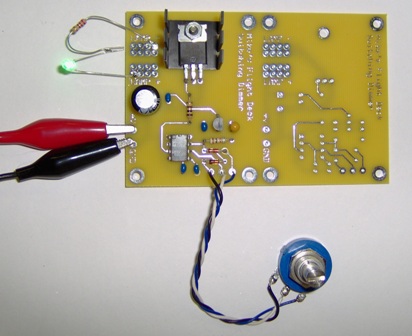
Once again I used the services of ExpressPCB. The board is 3.8" x 2.5". This is the special, low cost size which is bigger than needed, but you get three boards for $51 plus shipping and tax. So, I put two dimmers on the board.
I'll be posting the design file for the board along with an intro to the board design process over at MyCockpit next month.
LED Articles and Switching Dimmers (21 July 2010)
I've posted a few more Mike's Tips articles over at MyCockpit. One is about LED basics. The other covers operating LEDs in series and switching-type dimmers. There's a schematic for a simple dimmer based on the venerable 555 and an inexpensive power FET. The next article will cover making a PC board for the dimmer.
Mike's Tips on MyCockpit (15 April 2010)
I'm now writing a monthly article over at MyCockpit. Last month I wrote about choosing potentiometers for use as position sensors. This month I've put together some thoughts about Hall position sensors, should be up in a day or so.
Scribd is a community publishing site. People can upload whatever (with some limitations) they think might be of interest to others. Of interest to the flight sim community are the public domain military tech manuals. I stumbled across the operator's manual for the UH-60 Blackhawk helicopter. I also ran across manuals for the AH-64 and the F-16.
Projection Depth of Field (6 February 2010)
I've been investigating depth of field as applied to projection systems. There's a lot written about DoF when taking pictures, but little specifically about it when projecting an image. As it turns out, it's not difficult to derive DoF formulas from basics. It's really a question of geometry and how sharp-eyed you are.
DoF isn't really about focus. It's about an acceptable range of almost-in-focus. DoF in photography is based on the idea that a disk 0.01" (0.25mm) in diameter viewed at a distance of one foot (30 cm) is just barely distinguishable from a dimensionless point of equal brightness. There is some argument about this. Some use a slightly larger disk. Others say an image de-focused this much would be objectionably fuzzy. The arguments are really a matter of degree rather than of basic concept.
The fundamental concept is that there is a zone in front a lens within which objects will appear to be acceptably sharp. For photography, this plays out as detail or softness of objects in a print. For projection it is the sharpness of the image relative to the distance between the screen and lens for a given focus setting on the lens.
Disregarding any geometric distortion, projection DoF is an issue when you want to project onto something other than a flat screen orthogonal to the projection screen axis. For example, perhaps your projector doesn't have lens shift and you want to use an non-orthogonal projection angle. Or maybe you want to project onto a curved screen and want to know the minimum radius of curvature before focus becomes an issue.
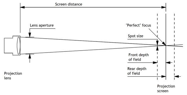
So, here are the basics. When a projection system is perfectly focused, a dimensionless point on the screen is illuminated by a conical bundle of light rays that extend from every point within the lens exit aperture and converge on the point on the screen. If the screen is moved closer to the screen, the screen intercepts a circular area of the cone. The closer the screen is, the larger the area of the circular intercept, and the more de-focused the point appears.
Now for the geometry: remember similar triangles, long, long ago in grade school? No? Well, anyway... The proportion of the spot size to the front depth of focus boundary is the same as the proportion of the lens aperture to the screen distance.
There are a few more details to consider.
Lens aperture in the drawing is the diameter of the lens exit aperture, not the f number. Lens aperture diameter is the lens focal length divided by the f number.
Spot size is the acceptable de-focusing of a theoretical point. It depends on how far away the viewer is from the screen. The 0.01" number is for a one foot viewing distance. If viewed from five feet, it can be five times as large. On the other hand, this is the spot size that is just visible to a viewer of average visual acuity. Perhaps you have better than average eye sight, or simply don't want the de-focusing to be noticeable at all. In those cases, your choice of acceptable spot size might be one half or one third the size with a commensurate reduction in DoF.
Depth of Field is an objective calculation that increases with projection distance and viewing distance, but decreases with increasing lens exit diameter. Depth of Field is also a somewhat subjective concept that depends on the acuity of a human viewer.
Interfacing a Real A/C Exhaust Gas Temperature Gauge - part 2 (16 January 2010)
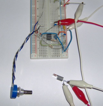
The firmware for the EGT adapter is complete and tested on a proto board. The PIC is the chip on the left of the proto board. The read and white clip leads hooked to the output of the PWM output filter. The other ends of the leads connect to a digital voltmeter. The components to the right of the white clip lead form the voltage inverter which is part of the tachometer adapter I tested earlier.

This test set up uses a signal generator to make pulses like the RC servo control pulses. The voltmeter readings verified that the voltage from the PWM filter varies from 0 to 40 millivolts as needed by the EGT gauge. I've sent a programmed PIC to Rob for testing with an OC servo card and a real EGT gauge. Soon we'll get a real world test.
You can download the assembly code here.
Interfacing a Real A/C Exhaust Gas Temperature Gauge (10 January 2010)
This is a spinoff from the tachometer interfacing project below. What we want to do here is interface a different type gauge using the same OpenCockpits RC servo control card. The EGT (exhaust gas temperature) gauge is an electronic instrument designed to respond to the low voltage output of a thermocouple. Rob has made a few measurements and determined that a 40 millivolt input will cause a full scale deflection.
Rather than start we're just going to modify the tachometer adapter. We'll replace the PIC firmware that generates the variable frequency square wave output used to drive the tach with a fixed frequency, variable duty cycle output. We'll also replace the tachometer-driving output transistor with a resistor-capacitor network which will scale the output voltage from the 5 volt max sent by the PIC to 40 millivolts, the max needed by the EGT. The caps in the network will filter the EGT control signal so the gauge sees a smooth voltage rather than the pulsating PIC output.
Here's where we are now:

And we have an early printed circuit design as well:

This board actually combines a single EGT adapter with a pair of tach adapters.
This is why I like microcontrollers, neat projects for not very much cash. (PIC16F648As are selling for $2.25 a piece from Jameco.)
Interfacing a Real A/C Tachometer - part 3 (8 January 2010)
The firmware is operating properly with sets signals. Rob will check its functionality with a real tachometer.
Here's the complete schematic. The whole thing is powered by the RC servo interface card. The card supplies +5 volts to power the servo. We use the 5 volts for the PIC and for a low power inverter.

And here's an early pass at circuit board artwork. This places three PICs on a single board along with a shared inverter for the output transistors.

Interfacing a Real A/C Tachometer - part 2 (3 January 2010)
As we left this project, my collaborator, Rob, was going to use the test oscillator diagramed in the December 9th note to try driving a real aircraft tachometer, and to get some measurements we could use to determine the tach's input resistance. Turns out the oscillator would not make the tach function. Rob also tried connecting the audio signal that drives his computer speakers, and that did the trick. He used a small audio signal generator app to produce a sine wave signal, and the tach woke up.
This told use that the tach worked and that we needed a drive signal that went negative in addition to going positive. And while the first version of the test oscillator did not do that and could not activate the tach display, it did provide us with test voltage measurements that allowed us to calculate the tach's input resistance. We needed to know this so we could determine how much power was needed to drive it.
All that lead us to a revised version of the test oscillator, shown below. Why stay with this when we knew we could drive the tach with an audio sine wave? Because the test oscillator signal is very easy to generate.
Version 2 of the test oscillator proved successful. We now know how to drive the tach with an easily made signal.

This brings us to the next step, developing a low cost interface.
As it turns out, Rob already has an OpenCockpits RC servo interface card. So not only does he have a chunk of nice hardware, he has the supporting software behind it. Software to bridge the gap between the flight simulation application and the interface hardware is a significant part of the project. So, our thought is that if we could somehow convert the RC servo style control pulse to the variable frequency square ware needed by the tach, we'd have a simple, low-cost solution.
This adapter is the approach we're working on now. It's based on a PIC16F648A micro controller. As you can see in the next figure, it doesn't take much hardware to make it go. Even after adding a small inverter to generate the -5 volt supply, we'll still be looking at only about $10 in parts. The bulk of the functionality comes from the firmware running on the PIC.
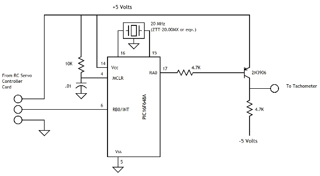
In general terms, the PIC uses an internal timer to measure the width of the RC servo control signal connected to pin 6. It does some scaling, checking, and binary hand-waving to calculate the parameter needed to generate a suitable tach control signal which it outputs though pin 17. The transistor makes sure the signal swings both below and above the 0 volt line.
At this point, I've got the firmware written, but not fully tested. Hopefully, I'll get to it over the next few days.